


1 Scope*
1.1 This specification
2 covers seamless and welded black and hot-dipped galvanized steel pipe in NPS 1
⁄8 to NPS 26 [DN 6 to DN 650] (Note 1), inclusive, with nominal wall thickness (Note 2) as given in Table X2.2 and Table X2.3. It shall be permissible to furnish pipe having other dimensions provided that such pipe complies with all other requirements of this specification. Supplementary requirements of an optional nature are provided and shall apply only when specified by the purchaser.
NOTE 1—The dimensionless designators NPS (nominal pipe size) [DN (diameter nominal)] have been substituted in this specification for such traditional terms as “nominal diameter,” “size,” and “nominal size.”
NOTE 2—The term nominal wall thickness has been assigned for the purpose of convenient designation, existing in name only, and is used to distinguish it from the actual wall thickness, which may vary over or under the nominal wall thickness.
1.2 This specification covers the following types and grades:
1.2.1 Type F—Furnace-butt-welded, continuous welded Grade A,
1.2.2 Type E—Electric-resistance-welded, Grades A and B, and
1.2.3 Type S—Seamless, Grades A and B.
NOTE 3—See Appendix X1 for definitions of types of pipe.
1.3 Pipe ordered under this specification is intended for mechanical and pressure applications and is also acceptable for ordinary uses in steam, water, gas, and air lines. It is suitable for welding, and suitable for forming operations involving coiling, bending, and flanging, subject to the following qualifications:
1.3.1 Type F is not intended for flanging.
1.3.2 If Type S or Type E is required for close coiling or cold bending, Grade A is the preferred grade; however, this is not intended to prohibit the cold bending of Grade B pipe.
1.3.3 Type E is furnished either nonexpanded or cold expanded at the option of the manufacturer.
1.4 The values stated in either SI units or inch-pound units are to be regarded separately as standard. The values stated in each system may not be exact equivalents; therefore, each system shall be used independently of the other. Combining values from the two systems may result in non-conformance with the standard.
1.5 The following precautionary caveat pertains only to the test method portion, Sections 7, 8, 9, 13, 14, and 15 of this specification: This standard does not purport to address all of the safety concerns, if any, associated with its use. It is the responsibility of the user of this standard to establish appropriate safety and health practices and determine the applicability of regulatory requirements prior to use.
1.6 The text of this specification contains notes or footnotes, or both, that provide explanatory material. Such notes and footnotes, excluding those in tables and figures, do not contain any mandatory requirements.
2 Referenced Documents
2.1 ASTM Standards:
3
A90/A90M Test Method for Weight [Mass] of Coating on Iron and Steel Articles with Zinc or Zinc-Alloy Coatings A370 Test Methods and Definitions for Mechanical Testing of Steel Products
A530/A530M Specification for General Requirements for Specialized Carbon and Alloy Steel Pipe
A700 Practices for Packaging, Marking, and Loading Methods for Steel Products for Shipment
1 This specification is under the jurisdiction of ASTM Committee A01 on Steel, Stainless Steel and Related Alloys and is the direct responsibility of Subcommittee A01.09 on Carbon Steel Tubular Products.
Current edition approved Oct. 1, 2010. Published November 2010. Originally approved in 1915. Last previous edition approved in 2007 as A53/A53M–07. DOI: 10.1520/A0053_A0053M-10.
2 For ASME Boiler and Pressure Vessel Code applications, see related Specification SA-53 in Section II of that code.
3 For referenced ASTM standards, visit the ASTM website, www.astm.org, or contact ASTM Customer Service at service@astm.org. For Annual Book of ASTM Standards volume information, refer to the standard’s Document Summary page on the ASTM website.
A751 Test Methods, Practices, and Terminology for Chemical Analysis of Steel Products
A865 Specification for Threaded Couplings, Steel, Black or Zinc-Coated (Galvanized) Welded or Seamless, for Use in Steel Pipe Joints B6 Specification for Zinc
E29 Practice for Using Significant Digits in Test Data to Determine Conformance with Specifications
E213 Practice for Ultrasonic Testing of Metal Pipe and Tubing
E273 Practice for Ultrasonic Testing of the Weld Zone of Welded Pipe and Tubing
E309 Practice for Eddy-Current Examination of Steel Tubular Products Using Magnetic Saturation
E570 Practice for Flux Leakage Examination of Ferromagnetic Steel Tubular Products
E1806 Practice for Sampling Steel and Iron for Determination of Chemical Composition
2.2 ANSI Standards:
ASC X12
4
B1.20.1 Pipe Threads, General Purpose
4
2.3 ASME Standard:
B36.10M Welded and Seamless Wrought Steel Pipe
5
2.4 Military Standards:
MIL-STD-129 Marking for Shipment and Storage
6
MIL-STD-163 Steel Mill Products Preparation for Shipment and Storage
6
2.5 Federal Standards:
Fed. Std. No. 123 Marking for Shipment (Civil Agencies)
7
Fed. Std. No. 183 Continuous Identification Marking of Iron and Steel Products
7
2.6 API Standard:
5B Specification for Threading, Gauging, and Thread Inspection of Casing, Tubing, and Line Pipe Threads
8
3 Ordering Information
3.1 Information items to be considered, if appropriate, for inclusion in the purchase order are as follows:
3.1.1 Specification designation (A53 or A53M, including year-date),
3.1.2 Quantity (feet, metres, or number of lengths),
3.1.3 Grade (A or B),
3.1.4 Type (F, E, or S; see 1.2),
3.1.5 Finish (black or galvanized),
3.1.6 Size (either nominal (NPS) [DN] and weight class or schedule number, or both; or outside diameter and wall thickness, see Table X2.2 and Table X2.3),
3.1.7 Length (specific or random, see Section 16),
3.1.8 End finish (plain end or threaded, Section 11),
4 Available from American National Standards Institute (ANSI), 25 W. 43rd St., 4th Floor, New York, NY 10036, http://www.ansi.org.
5 Available from American Society of Mechanical Engineers (ASME), ASME International Headquarters, Three Park Ave., New York, NY 10016-5990, http:// www.asme.org.
6 Available from Standardization Documents Order Desk, DODSSP, Bldg. 4, Section D, 700 Robbins Ave., Philadelphia, PA 19111-5098
7 Available from General Services Administration, Washington, DC 20405.
8 Available from American Petroleum Institute (API), 1220 L. St., NW, Washington, DC 20005-4070, http://api-ec.api.org.
3.1.8.1 Threaded and coupled, if desired,
3.1.8.2 Threads only (no couplings), if desired,
3.1.8.3 Plain end, if desired,
3.1.8.4 Couplings power tight, if desired,
3.1.8.5 Taper-tapped couplings for NPS 2 [DN 50] and smaller, if desired,
3.1.9 Close coiling, if desired (see 7.2.2),
3.1.10 Nondestructive electric test for seamless pipe (see 9.2),
3.1.11 Certification (see Section 20),
3.1.12 Report of the length of the end effect, if desired (see 9.2.7),
3.1.13 Marking (see Section 21),
3.1.14 End use of pipe,
3.1.15 Special requirements,
3.1.16 Supplementary requirements, if any,
3.1.17 Selection of applicable level of preservation and packaging and level of packing required, if other than as specified or if MIL-STD-163 applies (see 22.1), and
3.1.18 Packaging and package marking, if desired (see 23.1).
4 Materials and Manufacture
4.1 The steel for both seamless and welded pipe shall be made by one or more of the following processes: open-hearth, electric-furnace, or basic-oxygen.
4.2 If steels of different grades are sequentially strand cast, identification of the resultant transition material is required. The steel producer shall remove the transition material by any established procedure that positively separates the grades.
4.3 The weld seam of electric-resistance welded pipe in Grade B shall be heat treated after welding to a minimum of 1000 °F [540 °C] so that no untempered martensite remains, or otherwise processed in such a manner that no untempered martensite remains.
4.4 When pipe is cold expanded, the amount of expansion shall not exceed 1
1
⁄2 % of the specified outside diameter of the pipe.
5 Chemical Composition
5.1 The steel shall conform to the requirements as to chemical composition given in Table 1 and the chemical analysis shall be in accordance with Test Methods, Practices, and Terminology A751.
6 Product Analysis
6.1 The purchaser is permitted to perform an analysis of two pipes from each lot of 500 lengths, or fraction thereof. Samples for chemical analysis, except for spectrographic analysis, shall be taken in accordance with Practice E1806. The chemical composition thus determined shall conform to the requirements given in Table 1.
6.2 If the analysis of either pipe does not conform to the requirements given in Table 1, analyses shall be made on additional pipes of double the original number from the same lot, each of which shall conform to the specified requirements.
7 Mechanical Properties
7.1 Tension Test:
e = minimum elongation in 2 in. or 50 mm in percent, rounded to the nearest percent,
| Composition, max, % | |||||||||
| Carbon | Manganese | Phosphorus | Sulfur | CopperA | NickelA | ChromiumA | MolybdenumA | VanadiumA | |
| Type S (seamless pipe) | |||||||||
| Grade A | 0.25 | 0.95 | 0.05 | 0.045 | 0.40 | 0.40 | 0.40 | 0.15 | 0.08 |
| Grade B | 0.30 | 1.20 | 0.05 | 0.045 | 0.40 | 0.40 | 0.40 | 0.15 | 0.08 |
| Type E (electric-resistance-welded) | |||||||||
| Grade A | 0.25 | 0.95 | 0.05 | 0.045 | 0.40 | 0.40 | 0.40 | 0.15 | 0.08 |
| Grade B | 0.30 | 1.20 | 0.05 | 0.045 | 0.40 | 0.40 | 0.40 | 0.15 | 0.08 |
| Type F (furnace-welded pipe) | |||||||||
| Grade A | 0.30 | 1.20 | 0.05 | 0.045 | 0.40 | 0.40 | 0.40 | 0.15 | 0.08 |
7.1.1 For tension tests other than transverse weld tension tests, the yield strength corresponding to a permanent offset of 0.2 % of the gage length or to an extension of 0.5 % of the gage length under load, the tensile strength, and the elongation in 2 in. or 50 mm shall be determined, and the tension test results shall conform to the applicable tensile property requirements given in Table 2.
7.1.2 For transverse weld tension tests, the tensile strength shall be determined, and the tension test results shall conform to the applicable tensile strength requirement given in Table 2.
7.1.3 Electric-resistance-welded pipe NPS 8 [DN 200] or larger shall be tested using two transverse test specimens, one taken across the weld and one taken opposite the weld.
7.1.4 Transverse tension test specimens shall be approximately 1
1
⁄2 in. [38 mm] wide in the gage length and shall represent the full wall thickness of the pipe from which the test specimens were cut.
7.2 Bend Test:
7.2.1 For pipe NPS 2 [DN 50] or smaller, a sufficient length of pipe shall be capable of being bent cold through 90° around a cylindrical mandrel, the diameter of which is twelve times the specified outside diameter of the pipe, without developing cracks at any portion and without opening the weld.
7.2.2 If ordered for close coiling, the pipe shall stand being bent cold through 180° around a cylindrical mandrel, the diameter of which is eight times the specified outside diameter of the pipe, without failure.
7.2.3 Double-extra-strong pipe over NPS 1
1
⁄4 [DN 32] need not be subjected to the bend test.
| Grade A | Grade B | |
| Tensile strength, min, psi [MPa] | 48 000 [330] | 60 000 [415] |
| Yield strength, min, psi [MPa] | 30 000 [205] | 35 000 [240] |
| Elongation in 2 in. or 50 mm | A,B | A,B |
e = 6 2 5 0 0 0 [ 1 9 4 0 ] A ^ {0. 2} / U ^ {0. 9}
U = specified minimum tensile strength, psi [MPa].
B See Table X4.1 or Table X4.2, whichever is applicable, for the minimum elongation values that are required for various combinations of tension test specimen size and specified minimum tensile strength.
7.3 Flattening Test:
7.3.1 The flattening test shall be made on welded pipe over NPS 2 [DN 50] in extra-strong weight or lighter.
7.3.2 Seamless Pipe:
7.3.2.1 Although testing is not required, pipe shall be capable of meeting the flattening test requirements of Supplementary Requirement S1, if tested.
7.3.3 Electric-Resistance-Welded Pipe:
7.3.3.1 A test specimen at least 4 in. [100 mm] in length shall be flattened cold between parallel plates in three steps, with the weld located either 0° or 90° from the line of direction of force as required by 7.3.3.2 or 7.3.3.3, whichever is applicable. During the first step, which is a test for ductility of the weld, except as allowed by 7.3.5, 7.3.6, and 7.3.7, no cracks or breaks on the inside or outside surface at the weld shall be present before the distance between the plates is less than two thirds of the specified outside diameter of the pipe. As a second step, the flattening shall be continued as a test for ductility away from the weld. During the second step, except as allowed by 7.3.6 and 7.3.7, no cracks or breaks on the inside or outside surface away from the weld shall be present before the distance between the plates is less than one third of the specified outside diameter of the pipe but is not less than five times the specified wall thickness of the pipe. During the third step, which is a test for soundness, the flattening shall be continued until the test specimen breaks or the opposite walls of the test specimen meet. Evidence of laminated or unsound material or of incomplete weld that is revealed by the flattening test shall be cause for rejection.
7.3.3.2 For pipe produced in single lengths, the flattening test specified in 7.3.3.1 shall be made using a test specimen taken from each end of each length of pipe. The tests from each end shall be made alternately with the weld at 0° and at 90° from the line of direction of force.
7.3.3.3 For pipe produced in multiple lengths, the flattening test specified in 7.3.3.1 shall be made as follows:
(1) Test specimens taken from, and representative of, the front end of the first pipe intended to be supplied from each coil, the back end of the last pipe intended to be supplied from each coil, and each side of any intermediate weld stop location shall be flattened with the weld located at 90° from the line of direction of force.
(2) Test specimens taken from pipe at any two locations intermediate to the front end of the first pipe and the back end of the last pipe intended to be supplied from each coil shall be flattened with the weld located at 0° from the line of direction of force.
A = the lesser of 0.75 in.
2 [500 mm
2
] and the cross-sectional area of the tension test specimen, calculated using the specified outside diameter of the pipe, or the nominal width of the tension test specimen and the specified wall thickness of the pipe, with the calculated value rounded to the nearest 0.01 in.
2 [1 mm
2
], and
7.3.3.4 For pipe that is to be subsequently reheated throughout its cross section and hot formed by a reducing process, the manufacturer shall have the option of obtaining the flattening test specimens required by 7.3.3.2 or 7.3.3.3, whichever is applicable, either prior to or after such hot reducing.
7.3.4 Continuous-Welded Pipe—A test specimen at least 4 in. [100 mm] in length shall be flattened cold between parallel plates in three steps. The weld shall be located at 90° from the line of direction of force. During the first step, which is a test for ductility of the weld, except as allowed by 7.3.5, 7.3.6, and 7.3.7, no cracks or breaks on the inside, outside, or end surfaces at the weld shall be present before the distance between the plates is less than three fourths of the specified outside diameter of the pipe. As a second step, the flattening shall be continued as a test for ductility away from the weld. During the second step, except as allowed by 7.3.6 and 7.3.7, no cracks or breaks on the inside, outside, or end surfaces away from the weld shall be present before the distance between the plates is less than 60 % of the specified outside diameter of the pipe. During the third step, which is a test for soundness, the flattening shall be continued until the test specimen breaks or the opposite walls of the test specimen meet. Evidence of laminated or unsound material or of incomplete weld that is revealed by the flattening test shall be cause for rejection.
7.3.5 Surface imperfections in the test specimen before flattening, but revealed during the first step of the flattening test, shall be judged in accordance with the finish requirements in Section 12.
7.3.6 Superficial ruptures as a result of surface imperfections shall not be cause for rejection.
7.3.7 For pipe with a D-to-t ratio less than 10, because the strain imposed due to geometry is unreasonably high on the inside surface at the 6 and 12 o’clock locations, cracks at such locations shall not be cause for rejection.
8 Hydrostatic Test
8.1 The hydrostatic test shall be applied, without leakage through the weld seam or the pipe body.
8.2 Plain-end pipe shall be hydrostatically tested to the applicable pressure given in Table X2.2, and threaded-and-coupled pipe shall be hydrostatically tested to the applicable pressure given in Table X2.3. It shall be permissible, at the discretion of the manufacturer, to perform the hydrostatic test on pipe with plain ends, with threads only, or with threads and couplings; and it shall also be permissible to test pipe in either single lengths or multiple lengths. NOTE 4—The hydrostatic test pressures given herein are inspection test pressures, are not intended as a basis for design, and do not have any direct relationship to working pressures.
8.3 The minimum hydrostatic test pressure required to satisfy the requirements specified in 8.2 need not exceed 2500 psi [17 200 kPa] for pipe NPS 3 [DN 80] or smaller, or 2800 psi [19 300 kPa] for pipe larger than NPS 3 [DN 80]; however, the manufacturer has the option of using higher test pressures. For all sizes of seamless pipe and electric-resistance-welded pipe, the hydrostatic test pressure shall be maintained for at least 5 s.
9 Nondestructive Electric Test
9.1 Type E Pipe:
9.1.1 Except for pipe produced on a hot-stretch reducing mill, the weld seam of each length of electric-resistancewelded pipe NPS 2 [DN 50] or larger shall be tested with a nondestructive electric test in accordance with Practices E213, E273, E309, or E570. Each length of electric-resistancewelded pipe NPS 2 [DN 50] or larger and produced on a hot-stretch-reducing mill shall be tested with a nondestructive electric test that inpsects the full volume of the pipe in accordance with Practices E213, E309, or E570.
9.1.2 Ultrasonic and Electromagnetic Inspection—Any equipment utilizing the ultrasonic or electromagnetic principles and capable of continuous and uninterrupted inspection of the weld seam shall be used. The equipment shall be checked with an applicable reference standard as described in 9.1.3 at least once every working turn or not more than 8 h to demonstrate its effectiveness and the inspection procedures. The equipment shall be adjusted to produce well-defined indications when the reference standard is scanned by the inspection unit in a manner simulating the inspection of the product.
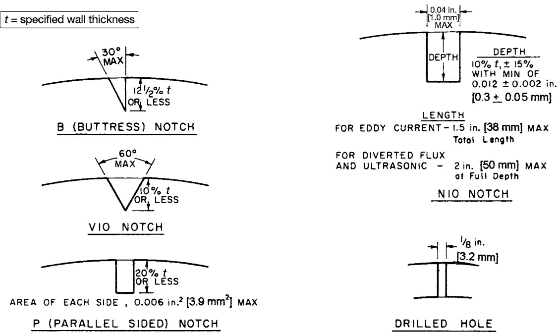
9.1.3 Reference Standards—The length of the reference standards shall be determined by the pipe manufacturer, and they shall have the same specified diameter and thickness as the product being inspected. Reference standards shall contain machined notches, one on the inside surface and one on the outside surface, or a drilled hole, as shown in Fig. 1, at the option of the pipe manufacturer. The notches shall be parallel to the weld seam, and shall be separated by a distance sufficient to produce two separate and distinguishable signals. The 1
⁄8-in. [3.2-mm] hole shall be drilled through the wall and perpendicular to the surface of the reference standard as shown in Fig. 1. Care shall be taken in the preparation of the reference standard to ensure freedom from fins or other edge roughness, or distortion of the pipe. NOTE 5—The calibration standards shown in Fig. 1 are convenient standards for calibration of nondestructive testing equipment. The dimensions of such standards are not to be construed as the minimum sizes of imperfections detectable by such equipment.
9.1.4 Acceptance Limits—Table 3 gives the height of acceptance limit signals in percent of the height of signals produced by reference standards. Imperfections in the weld seam that produce a signal greater than the acceptance limit signal given in Table 3 shall be considered a defect unless the pipe manufacturer can demonstrate that the imperfection does not reduce the effective wall thickness beyond 12.5 % of the specified wall thickness.
9.2 Type S Pipe—As an alternative to the hydrostatic test at the option of the manufacturer or if specified in the purchase order, the full body of each seamless pipe shall be tested with a nondestructive electric test in accordance with Practice E213, E309, or E570. In such cases, each length so furnished shall include the mandatory marking of the letters “NDE.” Except as allowed by 9.2.6.2, it is the intent of this nondestructive electric test to reject pipe with imperfections that produce test signals equal to or greater than those produced by the applicable calibration standards.
| Type Notch | Size of Hole | Acceptance Limit Signal, % | |
| in. | mm | ||
| N10, V10 | 1/8 | 3.2 | 100 |
| B, P | ... | ... | 80 |
9.2.1 If the nondestructive electric test has been performed, the lengths shall be marked with the letters “NDE.” The certification, if required, shall state Nondestructive Electric Tested and shall indicate which of the tests was applied. Also, the letters NDE shall be appended to the product specification number and grade shown on the certification.
9.2.2 The following information is intended to facilitate the use of this specification:
9.2.2.1 The calibration standards defined in 9.2.3 through 9.2.5 are convenient standards for calibration of nondestructive testing equipment. The dimensions of such standards are not to be construed as the minimum sizes of imperfections detectable by such equipment.
9.2.2.2 The ultrasonic testing referred to in this specification is capable of detecting the presence and location of significant longitudinally or circumferentially oriented imperfections; however, different techniques need to be employed for the detection of differently oriented imperfections. Ultrasonic testing is not necessarily capable of detecting short, deep imperfections.
9.2.2.3 The eddy current examination referenced in this specification has the capability of detecting significant discontinuities, especially of the short abrupt type.
9.2.2.4 The flux leakage examination referred to in this specification is capable of detecting the presence and location of significant longitudinally or transversely oriented discontinuities. The provisions of this specification only require
longitudinal calibration for flux leakage. Different techniques need to be employed for the detection of differently oriented imperfections.
9.2.2.5 The hydrostatic test referred to in 8.2 has the capability of finding imperfections of a size permitting the test fluid to leak through the tube wall and may be either visually seen or detected by a loss of pressure. Hydrostatic testing is not necessarily capable of detecting very tight through-the-wall imperfections or imperfections that extend an appreciable distance into the wall without complete penetration.
9.2.2.6 A purchaser interested in ascertaining the nature (type, size, location, and orientation) of imperfections that are capable of being detected in the specific application of these examinations is directed to discuss this with the manufacturer of the tubular product.
9.2.3 For ultrasonic testing, the calibration reference notches shall be at the option of the manufacturer, and shall be any one of the three common notch shapes shown in Practice E213. The depth of notch shall not exceed 12.5 % of the specified wall thickness of the pipe or 0.004 in. [0.1 mm], whichever is the greater.
9.2.4 For eddy current testing, the calibration pipe shall contain, at the option of the manufacturer, any one of the following calibration standards to establish a minimum sensitivity level for rejection.
9.2.4.1 Drilled Hole—The calibration pipe shall contain three holes spaced 120° apart or four holes spaced 90° apart, sufficiently separated longitudinally to ensure separately distinguishable responses. The holes shall be drilled radially and completely through the pipe wall, care being taken to avoid distortion of the pipe while drilling. Dependent upon the nominal pipe size, the calibration pipe shall contain the following hole:
| NPS | DN | Diameter of Drilled Hole |
| ≤1/2 | ≤15 | 0.039 in. [1.0 mm] |
| >1/2 | >15 | 0.055 in. [1.4 mm] |
| ≤ | ≤32 | |
| 11/4 | ||
| > | >32 | 0.071 in. [1.8 mm] |
| 11/4 | ≤50 | |
| ≤2 | ||
| >2 | >50 | 0.087 in. [2.2 mm] |
| ≤5 | ≤ | |
| 125 | ||
| >5 | > | 0.106 in. [2.7 mm] |
| 125 |
9.2.4.2 Transverse Tangential Notch—Using a round tool or file with a 1⁄4 in. [6 mm] diameter, a notch shall be filed or milled tangential to the surface and transverse to the longitudinal axis of the pipe. The notch shall have a depth not exceeding 12.5 % of the specified wall thickness of the pipe or 0.012 in. [0.3 mm], whichever is the greater.
9.2.4.3 Longitudinal Notch—A notch 0.031 in. [0.8 mm] or less in width shall be machined in a radial plane parallel to the pipe axis on the outside surface of the pipe, to a depth not exceeding 12.5 % of the specified wall thickness of the pipe or 0.012 in. [0.3 mm], whichever is the greater. The length of the notch shall be compatible with the testing method.
9.2.4.4 Compatibility—The calibration standards in the calibration pipe shall be compatible with the testing equipment and the method being used.
9.2.5 For flux leakage testing, the longitudinal calibration reference notches shall be straight-sided notches machined in a radial plane parallel to the pipe axis. For specified wall thicknesses less than 0.500 in. [12.7 mm], outside and inside notches shall be used. For specified wall thicknesses equal to or greater than 0.500 in. [12.7 mm], only an outside notch shall be used. The notch depth shall not exceed 12.5 % of the specified wall thickness, or 0.012 in. [0.3 mm], whichever is the greater. The notch length shall not exceed 1 in. [25 mm], and the notch width shall not exceed the notch depth. Outside diameter and inside diameter notches shall be located sufficiently apart to allow separation and identification of the signals.
9.2.6 Pipe containing one or more imperfections that produce a signal equal to or greater than the signal produced by the calibration standard shall be rejected or the area producing the signal shall be rejected.
9.2.6.2 It shall be permissible to evaluate test signals produced by visual imperfections in accordance with the provisions of Section 12. A few examples of such imperfections are straightener marks, cutting chips, scratches, steel die stamps, stop marks, or pipe reducer ripple.
9.2.7 The test methods described in Section 9 are not necessarily capable of inspecting the end portion of pipes. This condition is referred to as end effect. The length of the end effect shall be determined by the manufacturer and, if specified in the purchase order, reported to the purchaser.
10 Permissible Variations in Weight (Mass) and Dimensions
10.1 Weight (Mass)—The weight (mass) of the pipe shall not vary more than 6 10 % from its specified weight (mass), as derived by multiplying its measured length by its specified weight (mass) per unit length, as given in Table X2.2 or Table X2.3, or as calculated using the relevant equation in ASME B36.10M. NOTE 6—For pipe NPS 4 [DN 100] or smaller, the weight (mass) tolerance is applicable to the weights (masses) of the customary lifts of pipe as produced for shipment by the mill. For pipe larger than NPS 4 [DN 100], where individual lengths are weighed, the weight (mass) tolerance is applicable to the individual lengths.
10.2 Diameter—For pipe NPS 1
1
⁄2 [DN 40] or smaller, the outside diameter at any point shall not vary more than 6 1
⁄64 in. [0.4 mm] from the specified outside diameter. For pipe NPS 2 [DN 50] or larger, the outside diameter shall not vary more than 6 1 % from the specified outside diameter.
10.3 Thickness—The minimum wall thickness at any point shall be not more than 12.5 % under the specified wall thickness. The minimum wall thickness on inspection shall conform to the requirements given in Table X2.4.
11 End Finish
11.1 If ordered with plain ends, the pipe shall be furnished to the following practice, unless otherwise specified.
11.1.1 NPS 1
1
⁄2 [DN 40] or Smaller—Unless otherwise specified in the purchase order, end finish shall be at the option of the manufacturer.
11.1.2 Larger than NPS 1
1
⁄2 [DN 40]:
11.1.2.1 Pipe of standard-weight or extra-strong weight, or in wall thickness less than 0.500 in. [12.7 mm], other than double extra-strong weight pipe, shall be plain-end beveled with ends beveled to an angle of 30°, +5°, -0°, measured from a line drawn perpendicular to the axis of the pipe, and with a root face of 1
⁄16 in. 6 1
⁄32 in. [1.6 mm 6 0.8 mm].
11.1.2.2 Pipe with a specified wall thickness greater than 0.500 in. [12.7 mm], and all double extra-strong weight pipe, shall be plain-end square cut.
11.2 If ordered with threaded ends, the pipe ends shall be provided with a thread in accordance with the gaging practice and tolerances of ANSI B1.20.1. For standard-weight pipe NPS 6 [DN 150] or smaller, refer to Table X3.1 for threading data. For standard-weight pipe NPS 8 [DN 200] or larger and all sizes of extra-strong weight pipe and double extra-strong weight pipe, refer to Table X3.2 for threading data. Threaded pipe NPS 4 [DN 100] or larger shall have thread protectors on the ends not protected by a coupling.
11.3 If ordered with couplings, one end of each length of pipe shall be provided with a coupling manufactured in accordance with Specification A865. The coupling threads shall be in accordance with the gaging practice of ANSI B1.20.1. The coupling shall be applied handling-tight, unless power-tight is specified in the purchase order. Couplings are to be made of steel. Taper-tapped couplings shall be furnished on all threaded pipe NPS 2
1
⁄2 [DN 65] or larger. For pipe smaller than NPS 2
1
⁄2 [DN 65], it is regular practice to furnish
straight-tapped couplings for standard-weight pipe and tapertapped couplings for extra-strong and double extra-strong weight pipe. If taper-tapped couplings are required for standard-weight pipe smaller than NPS 2
1
⁄2 [DN 65], it is recommended that line pipe threads in accordance with API Specification 5B be ordered. The taper-tapped couplings provided on line pipe in such sizes may be used on mill-threaded standard-weight pipe of the same size.
12 Workmanship, Finish, and Appearance
12.1 The pipe manufacturer shall explore a sufficient number of visual surface imperfections to provide reasonable assurance that they have been properly evaluated with respect to depth.
12.2 Surface imperfections that penetrate more than 12.5 % of the specified wall thickness or encroach on the minimum wall thickness shall be considered defects. Pipe with defects shall be given one or more of the following dispositions:
12.2.1 The defect shall be removed by grinding, provided that the remaining wall thickness is within specified limits,
12.2.2 Type S pipe and the parent metal of Type E pipe, except within 1⁄2 in. [13 mm] of the fusion line of the electric-resistance-weld seam, are permitted to be repaired in accordance with the welding provisions of 12.5. Repair welding of Type F pipe and the weld seam of Type E pipe is prohibited.
12.2.3 The section of pipe containing the defect shall be cut off within the limits of requirement on length, or
12.2.4 Rejected.
12.3 At the purchaser’s discretion, pipe shall be subjected to rejection if surface defects repaired in accordance with 12.2 are not scattered, but appear over a large area in excess of what is considered a workmanlike finish. Disposition of such pipe shall be a matter of agreement between the manufacturer and the purchaser.
12.4 For the removal of imperfections and defects by grinding, a smooth curved surface shall be maintained, and the wall thickness shall not be decreased below that permitted by this specification. It shall be permissible to reduce the outside diameter at the point of grinding by the amount so removed.
12.4.1 Wall thickness measurements shall be made with a mechanical caliper or with a properly calibrated nondestructive testing device of appropriate accuracy. In the case of a dispute, the measurement determined by use of the mechanical caliper shall govern.
12.5 Weld repair shall only be permitted with the approval of the purchaser and in accordance with Specification A530/ A530M.
12.6 The finished pipe shall be reasonably straight.
12.7 The pipe shall contain no dents greater than 10 % of the pipe diameter or 1⁄4 in. [6 mm], whichever is smaller, measured as the gap between the lowest point of the dent and a prolongation of the original contour of the pipe. Cold-formed dents deeper than 1
⁄8 in. [3 mm] shall be free of sharp-bottomed gouges; it shall be permissible to remove the gouges by grinding, provided that the remaining wall thickness is within specified limits. The length of the dent in any direction shall not exceed one half the specified outside diameter of the pipe.
13 Number of Tests
13.1 Except as required by 13.2, one of each of the tests specified in Section 7 shall be made on test specimens taken from one length of pipe from each lot of each pipe size. For continuous-welded pipe, each lot shall contain no more than 25 tons [23 Mg] of pipe for pipe sizes NPS 1
1
⁄2 [DN 40] and smaller, and no more than 50 tons [45 Mg] of pipe for pipe sizes larger than NPS 1
1
⁄2 [DN 40]. For seamless and electricresistance-welded pipe, a lot shall contain no more than one heat, and at the option of the manufacturer shall contain no more than 500 lengths of pipe (as initially cut after the final pipe-forming operation, prior to any further cutting to the required ordered lengths) or 50 tons [45 Mg] of pipe.
13.2 The number of flattening tests for electric-resistancewelded pipe shall be in accordance with 7.3.3.2 or 7.3.3.3, whichever is applicable.
13.3 Except as allowed by 9.2, each length of pipe shall be subjected to the hydrostatic test (see Section 8).
14 Retests
14.1 Except for flattening tests of electric-resistance-welded pipe, if the results of a mechanical test for a lot fail to conform to the applicable requirements specified in Section 7, the lot shall be rejected unless tests of additional pipe from the affected lot of double the number originally tested are subsequently made and each such test conforms to the specified requirements. Only one retest of any lot will be permitted. Any individual length of pipe that conforms to the test requirements is acceptable. Any individual length of pipe that does not conform to the test requirements may be resubmitted for test and will be considered acceptable if tests taken from each pipe end conform to the specified requirements.
14.2 Electric-Resistance-Welded Pipe Produced in Single Lengths—If any flattening test result fails to conform to the requirements specified in 7.3.3, the affected single length shall be rejected unless the failed end is subsequently retested using the same weld orientation as the failed test and a satisfactory test result is obtained before the pipe’s length is reduced by such testing to less than 80 % of its length after the initial cropping.
14.3 Electric-Resistance-Welded Pipe Produced in Multiple Lengths—If any flattening test result fails to conform to the requirements specified in 7.3.3, the affected multiple length shall be rejected or flattening tests shall be made using a test specimen taken from each end of each individual length in the failed multiple length. For each pipe end, such tests shall be made with the weld alternately at 0° and 90° from the line of direction of force. Individual lengths are considered acceptable if the test results for both pipe ends conform to the specified requirements.
15 Test Methods
15.1 The test specimens and the tests required by this specification shall conform to those described in the latest issue of Test Methods and Definitions A370.
15.2 Each longitudinal tension test specimen shall be taken from a pipe end and shall not be flattened between the gage marks.
15.3 Test specimens for bend tests and flattening tests shall be taken from pipe. Test specimens for flattening tests shall be smooth on the ends and free from burrs.
15.4 Tests shall be conducted at room temperature.
16 Lengths
16.1 Unless otherwise specified, pipe lengths shall be in accordance with the following regular practices:
16.1.1 Except as allowed by 16.1.2 and 16.1.4, pipe lighter than extra-strong weight shall be in single-random lengths of 16 to 22 ft [4.88 to 6.71 m], with not more than 5 % of the total number of threaded lengths furnished being jointers (two pieces coupled together).
16.1.2 For plain-end pipe lighter than extra-strong weight, it shall be permissible for not more than 5 % of the total number of pipe to be in lengths of 12 to 16 ft [3.66 to 4.88 m].
16.1.3 Pipe of extra-strong weight or heavier shall be in random lengths of 12 to 22 ft [3.66 to 6.71 m], except that it shall be permissible for not more than 5 % of the total of pipe to be in lengths of 6 to 12 ft [1.83 to 3.66 m].
16.1.4 For extra-strong weight or lighter pipe ordered in double-random lengths, the minimum lengths shall be not less than 22 ft [6.71 m] and the minimum average length for the order shall be not less than 35 ft [10.67 m].
16.1.5 For pipe heavier than extra-strong weight ordered in lengths longer than single random, the lengths shall be as agreed upon between the manufacturer and the purchaser.
16.1.6 If pipe is furnished threaded and coupled, the length shall be measured to the outer face of the coupling.
17 Galvanized Pipe
17.1 Galvanized pipe ordered under this specification shall be coated with zinc inside and outside by the hot-dip process. The zinc used for the coating shall be any grade of zinc conforming to Specification B6.
17.2 Weight (Mass) per Unit Area of Coating—The weight (mass) per unit area of zinc coating shall be not less than 1.8 oz/ft
2 [0.55 kg/m
2
] as determined from the average results of the two specimens taken for test in the manner prescribed in 17.5 and not less than 1.6 oz/ft
2 [0.49 kg/m
2
] for each of these specimens. The weight (mass) per unit area of coating, expressed in ounces per square foot [kilograms per square metre] shall be calculated by dividing the total weight (mass) of zinc, inside plus outside, by the total area, inside plus outside, of the surface coated. Each specimen shall have not less than 1.3 oz/ft2[0.40kg/m2] of zinc coating on each surface, calculated by dividing the total weight (mass) of zinc on the given surface (outside or inside) by the area of the surface coated (outside or inside).
17.3 Weight (Mass) per Unit Area of Coating Test—The weight (mass) per unit area of zinc coating shall be determined by stripping tests in accordance with Test Method A90/A90M.
17.4 Test Specimens—Test specimens for determination of weight (mass) per unit area of coating shall be cut approximately 4 in. [100 mm] in length.
17.5 Number of Tests—Two test specimens for the determination of weight (mass) per unit area of coating shall be taken,
one from each end of one length of galvanized pipe selected at random from each lot of 500 lengths, or fraction thereof, of each size.
17.6 Retests—If the weight (mass) per unit area of coating of any lot does not conform to the requirements specified in 17.2, retests of two additional pipes from the same lot shall be made, each of which shall conform to the specified requirements.
17.7 If pipe ordered under this specification is to be galvanized, the tension, flattening, and bend tests shall be made on the base material before galvanizing, if practicable. If specified, results of the mechanical tests on the base material shall be reported to the purchaser. If it is impracticable to make the mechanical tests on the base material before galvanizing, it shall be permissible to make such tests on galvanized samples, and any flaking or cracking of the zinc coating shall not be considered cause for rejection. If galvanized pipe is bent or otherwise fabricated to a degree that causes the zinc coating to stretch or compress beyond the limit of elasticity, some flaking of the coating is acceptable.
18 Inspection
18.1 The inspector representing the purchaser shall have entry, at all times while work on the contract of the purchaser is being performed, to all parts of the manufacturer’s works that concern the manufacture of the pipe ordered. The manufacturer shall afford the inspector all reasonable facilities to be satisfied that the pipe is being furnished in accordance with this specification. All tests (except product analysis) and inspection shall be made at the place of manufacture prior to shipment, unless otherwise specified, and shall be so conducted as not to interfere unnecessarily with the operation of the works.
19 Rejection
19.1 The purchaser is permitted to inspect each length of pipe received from the manufacturer and, if it does not meet the requirements of this specification based upon the inspection and test method as outlined in the specification, the length shall be rejected and the manufacturer shall be notified. Disposition of rejected pipe shall be a matter of agreement between the manufacturer and the purchaser.
19.2 Pipe found in fabrication or in installation to be unsuitable for the intended use, under the scope and requirements of this specification, shall be set aside and the manufacturer notified. Such pipe shall be subject to mutual investigation as to the nature and severity of the deficiency and the forming or installation, or both, conditions involved. Disposition shall be a matter for agreement.
20 Certification
20.1 The manufacturer or supplier shall, upon request, furnish to the purchaser a certificate of compliance stating that the material has been manufactured, sampled, tested, and inspected in accordance with this specification (including year-date), and has been found to meet the requirements.
20.2 Test Report—For Types E and S, the manufacturer or supplier shall furnish to the purchaser a chemical analysis report for the elements given in Table 1.
20.3 EDI—A certificate of compliance or test report printed from, or used in, electronic form from an electronic data interchange (EDI) transmission shall be regarded as having the same validity as a counterpart printed in the certifier’s facility. The use and format of the EDI document are subject to agreement between the purchaser and the manufacturer or supplier. NOTE 7—EDI is the computer to computer exchange of business information in a standard format such as ANSI ASC X12.
20.4 Notwithstanding the absence of a signature, the organization submitting the certificate of compliance or test report is responsible for its content.
21 Product Marking
21.1 Except as allowed by 21.5 and 21.6, each length of pipe shall be legibly marked in the following sequence to show:
21.1.1 Manufacturer’s name or mark,
21.1.2 Specification number (year-date not required),
NOTE 8—Pipe that complies with multiple compatible specifications may be marked with the appropriate designation for each specification.
21.1.3 Size (NPS and weight class, schedule number, or specified wall thickness; or specified outside diameter and specified wall thickness),
21.1.4 Grade (A or B),
21.1.5 Type of pipe (F, E, or S),
21.1.6 Test pressure, seamless pipe only (if applicable, in accordance with Table 4),
21.1.7 Nondestructive electric test, seamless pipe only (if applicable, in accordance with Table 4),
21.2 Unless another marking format is specified in the purchase order, length shall be marked in feet and tenths of a foot, or metres to two decimal places, dependent upon the units to which the pipe was ordered. The location of such marking shall be at the option of the manufacturer.
21.3 Heat number, lot number, run number, or a combination thereof shall be marked at the option of the manufacturer, unless specific marking is specified in the purchase order. The location of such marking shall be at the option of the manufacturer.
| Hydro | NDE | Marking |
| Yes | No | Test pressure |
| No | Yes | NDE |
| Yes | Yes | Test Pressure/NDE |
21.4 Any additional information desired by the manufacturer or specified in the purchase order.
21.5 For pipe NPS 1
1
⁄2 [DN 40] and smaller that is bundled, it shall be permissible to mark the required information on a tag securely attached to each bundle.
21.6 If pipe sections are cut into shorter lengths by a processor for resale as pipe, the processor shall transfer the complete identification, including the name or brand of the manufacturer, to each unmarked cut length, or to metal tags securely attached to unmarked pipe bundled in accordance with the requirements of 21.5. The same material designation shall be included with the information transferred, and the processor’s name, trademark, or brand shall be added.
21.7 Bar Coding—In addition to the requirements in 21.1, 21.5, and 21.6, bar coding is acceptable as a supplementary identification method. It is recommended that bar coding be consistent with the Automotive Industry Action Group (AIAG) standard prepared by the Primary Metals Subcommittee of the AIAG Bar Code Project Team.
22 Government Procurement
22.1 If specified in the contract, the pipe shall be preserved, packaged, and packed in accordance with the requirements of MIL-STD-163. The applicable levels shall be as specified in the contract. Marking for shipment of such pipe shall be in accordance with Fed. Std. No. 123 for civil agencies and MIL-STD-129 or Fed. Std. No. 183 if continuous marking is required, for military agencies.
22.2 Inspection—Unless otherwise specified in the contract, the manufacturer is responsible for the performance of all inspection and test requirements specified herein. Except as otherwise specified in the contract, the manufacturer shall use its own or any other suitable facilities for performing the inspection and test requirements specified herein, unless otherwise disapproved by the purchaser in the contract or purchase order. The purchaser shall have the right to perform any of the inspections and tests set forth in this specification where deemed necessary to ensure that the pipe conforms to the specified requirements.
23 Packaging and Package Marking
23.1 If specified in the purchase order, packaging, marking, and loading for shipment shall be in accordance with those procedures recommended by Practices A700.
24 Keywords
24.1 black steel pipe; seamless steel pipe; steel pipe; welded steel pipe; zinc coated steel pipe
The following supplementary requirements shall apply only when specified in the purchase order. The purchaser may specify a different frequency of test than is provided in the supplementary requirement. Subject to agreement between the purchaser and manufacturer, retest and retreatment provisions of these supplementary requirements may also be modified.
S1. Flattening Test, Seamless Pipe
S1.1 A test specimen at least 2
1
⁄2 in. [60 mm] in length shall be flattened cold between parallel plates in two steps. During the first step, which is a test for ductility, except as allowed by S1.3, S1.4, and S1.5, no cracks or breaks on the inside, outside, or end surfaces shall be present before the distance between the plates is less than the value of H calculated as follows:
H = (1 + e) t / (e + t / D)
where:
H = distance between flattening plates, in. [mm],
e = deformation per unit length (constant for a given grade of steel, 0.09 for Grade A, and 0.07 for Grade B),
t = specified wall thickness, in. [mm], and
D = specified outside diameter, in. [mm]
The H values have been calculated for standard-weight and extra-heavy weight pipe from NPS 2
1
⁄2 to NPS 24 [DN 65 to DN 600], inclusive, and are given in Table X2.1.
S1.2 During the second step, which is a test for soundness, the flattening shall be continued until the test specimen breaks or the opposite sides of the test specimen meet. Evidence of laminated or unsound material that is revealed during the entire flattening test shall be cause for rejection.
S1.3 Surface imperfections in the test specimen before flattening, but revealed during the first step of the flattening test, shall be judged in accordance with the finish requirements in Section 12.
S1.4 Superficial ruptures as a result of surface imperfections shall not be cause for rejection.
S1.5 For pipe with a D-to-t ratio less than 10, because the strain imposed due to geometry is unreasonably high on the inside surface at the 6 and 12 o’clock locations, cracks at such locations shall not be cause for rejection.
S1.6 One test shall be made on test specimens taken from one length of pipe from each lot of each pipe size. A lot shall contain no more than one heat, and at the option of the manufacturer shall contain no more than 500 lengths of pipe (as initially cut after the final pipe-forming operation, prior to any further cutting to the required ordered lengths) or 50 tons [45 Mg] of pipe.
S1.7 If the results of a test for a lot fail to conform to the applicable requirements, the lot shall be rejected unless tests of additional pipe from the affected lot of double the number originally tested are subsequently made and each such test conforms to the specified requirements. Only one retest of any lot will be permitted. Any individual length of pipe that conforms to the test requirements is acceptable. Any individual length of pipe that does not conform to the test requirements may be resubmitted for test and will be considered acceptable if tests taken from each pipe end conform to the specified requirements.
APPENDIXES
(Nonmandatory Information)
X1. DEFINITIONS OF TYPES OF PIPE
X1.1 Type F, Furnace-Butt-Welded Pipe, Continuous-Welded Pipe—Pipe produced in multiple lengths from coiled skelp and subsequently cut into individual lengths, having its longitudinal butt joint forge welded by the mechanical pressure developed in rolling the hot-formed skelp through a set of round pass welding rolls.
X1.2 Type E, Electric-Resistance-Welded Pipe—Pipe produced in single lengths, or in multiple lengths from coiled skelp and subsequently cut into individual lengths, having a
longitudinal butt joint wherein coalescence is produced by the heat obtained from resistance of the pipe to the flow of electric current in a circuit of which the pipe is a part, and by the application of pressure.
X1.3 Type S, Seamless Pipe—Pipe made without a welded seam. It is manufactured by hot working steel and, if necessary, by subsequently cold finishing the hot-worked tubular product to produce the desired shape, dimensions, and properties.
X2. TABLES FOR DIMENSIONAL AND CERTAIN MECHANICAL REQUIREMENTS
X2.1 Tables X2.1-X2.4 address dimensional and certain mechanical requirements.
| NPS Designator | DN Designator | Specified Outside Diameter, in. [mm] | Specified Wall Thickness, in. [mm] | Distance, in. [mm], Between Plates “H” by Formula: H = (1 + e)t/(e + t/D) | |
| Grade A | Grade B | ||||
| 21/2 | 65 | 2.875 [73.0] | 0.203 [5.16] | 1.378 [35.0] | 1.545 [39.2] |
| 0.276 [7.01] | 1.618 [41.1] | 1.779 [45.2] | |||
| 3 | 80 | 3.500 [88.9] | 0.216 [5.49] | 1.552 [39.4] | 1.755 [44.6] |
| 0.300 [7.62] | 1.861 [47.3] | 2.062 [52.4] | |||
| 31/2 | 90 | 4.000 [101.6] | 0.226 [5.74] | 1.682 [42.7] | 1.912 [48.6] |
| 0.318 [8.08] | 2.045 [51.9] | 2.276 [57.8] | |||
| 4 | 100 | 4.500 [114.3] | 0.237 [6.02] | 1.811 [46.0] | 2.067 [52.5] |
| 0.337 [8.56] | 2.228 [56.6] | 2.489 [63.2] | |||
| 5 | 125 | 5.563 [141.3] | 0.258 [6.55] | 2.062 [52.4] | 2.372 [60.2] |
| 0.375 [9.52] | 2.597 [66.0] | 2.920 [74.2] | |||
| 6 | 150 | 6.625 [168.3] | 0.280 [7.11] | 2.308 [58.6] | 2.669 [67.8] |
| 0.432 [10.97] | 3.034 [77.1] | 3.419 [86.8] | |||
| 8 | 200 | 8.625 [219.1] | 0.277 [7.04] | 2.473 [62.8] | 2.902 [73.7] |
| 0.322 [8.18] | 2.757 [70.0] | 3.210 [81.5] | |||
| 0.500 [12.70] | 3.683 [93.5] | 4.181 [106.2] | |||
| 10 | 250 | 10.750 [273.0] | 0.279 [7.09]A | 2.623 [66.6] | 3.111 [79.0] |
| 0.307 [7.80] | 2.823 [71.7] | 3.333 [84.7] | |||
| 0.365 [9.27] | 3.210 [81.5] | 3.757 [95.4] | |||
| 0.500 [12.70] | 3.993 [101.4] | 4.592 [116.6] | |||
| 12 | 300 | 12.750 [323.8] | 0.300 [7.62] | 3.105 [78.9] | 3.683 [93.5] |
| 0.375 [9.52] | 3.423 [86.9] | 4.037 [102.5] | |||
| 0.500 [12.70] | 4.218 [107.1] | 4.899 [124.4] | |||
| 14 | 350 | 14.000 [355.6] | 0.375 [9.52] | 3.500 [88.9] | 4.146 [105.3] |
| 0.500 [12.70] | 4.336 [110.1] | 5.061 [128.5] | |||
| 16 | 400 | 16.000 [406.4] | 0.375 [9.52] | 3.603 [91.5] | 4.294 [109.1] |
| 0.500 [12.70] | 4.494 [114.1] | 5.284 [134.2] | |||
| 18 | 450 | 18.000 [457] | 0.375 [9.52] | 3.688 [93.7] | 4.417 [112.2] |
| 0.500 [12.70] | 4.628 [117.6] | 5.472 [139.0] | |||
| 20 | 500 | 20.000 [508] | 0.375 [9.52] | 3.758 [95.5] | 4.521 [114.8] |
| 0.500 [12.70] | 4.740 [120.4] | 5.632 [143.1] | |||
| 24 | 600 | 24.000 [610] | 0.375 [9.52] | 3.869 [98.3] | 4.686 [119.0] |
| 0.500 [12.70] | 4.918 [124.9] | 5.890 [149.6] | |||
| NPS Designator | DN Designator | Specified Outside Diameter, in. [mm] | Specified Wall Thickness, in. [mm] | Nominal Weight (Mass) per Unit Length, Plain End, lb/ft [kg/m] | Weight Class | Schedule No. | Test Pressure,A psi [kPa] | |
| Grade A | Grade B | |||||||
| 1/8 | 6 | 0.405 [10.3] | 0.068 [1.73] | 0.24 [0.37] | STD | 40 | 700 [4800] | 700 [4800] |
| 0.095 [2.41] | 0.31 [0.47] | XS | 80 | 850 [5900] | 850 [5900] | |||
| 1/4 | 8 | 0.540 [13.7] | 0.088 [2.24] | 0.43 [0.63] | STD | 40 | 700 [4800] | 700 [4800] |
| 0.119 [3.02] | 0.54 [0.80] | XS | 80 | 850 [5900] | 850 [5900] | |||
| 3/8 | 10 | 0.675 [17.1] | 0.091 [2.31] | 0.57 [0.84] | STD | 40 | 700 [4800] | 700 [4800] |
| 0.126 [3.20] | 0.74 [1.10] | XS | 80 | 850 [5900] | 850 [5900] | |||
| 1/2 | 15 | 0.840 [21.3] | 0.109 [2.77] | 0.85 [1.27] | STD | 40 | 700 [4800] | 700 [4800] |
| 0.147 [3.73] | 1.09 [1.62] | XS | 80 | 850 [5900] | 850 [5900] | |||
| 0.188 [4.78] | 1.31 [1.95] | ... | 160 | 900 [6200] | 900 [6200] | |||
| 0.294 [7.47] | 1.72 [2.55] | XXS | ... | 1000 [6900] | 1000 [6900] | |||
| 3/4 | 20 | 1.050 [26.7] | 0.113 [2.87] | 1.13 [1.69] | STD | 40 | 700 [4800] | 700 [4800] |
| 0.154 [3.91] | 1.48 [2.20] | XS | 80 | 850 [5900] | 850 [5900] | |||
| 0.219 [5.56] | 1.95 [2.90] | ... | 160 | 950 [6500] | 950 [6500] | |||
| 0.308 [7.82] | 2.44 [3.64] | XXS | ... | 1000 [6900] | 1000 [6900] | |||
| 1 | 25 | 1.315 [33.4] | 0.133 [3.38] | 1.68 [2.50] | STD | 40 | 700 [4800] | 700 [4800] |
| 0.179 [4.55] | 2.17 [3.24] | XS | 80 | 850 [5900] | 850 [5900] | |||
| 0.250 [6.35] | 2.85 [4.24] | ... | 160 | 950 [6500] | 950 [6500] | |||
| 0.358 [9.09] | 3.66 [5.45] | XXS | ... | 1000 [6900] | 1000 [6900] | |||
| 11/4 | 32 | 1.660 [42.2] | 0.140 [3.56] | 2.27 [3.39] | STD | 40 | 1200 [8300] | 1300 [9000] |
| 0.191 [4.85] | 3.00 [4.47] | XS | 80 | 1800 [12 400] | 1900 [13 100] | |||
| 0.250 [6.35] | 3.77 [5.61] | ... | 160 | 1900 [13 100] | 2000 [13 800] | |||
| 0.382 [9.70] | 5.22 [7.77] | XXS | ... | 2200 [15 200] | 2300 [15 900] | |||
| 11/2 | 40 | 1.900 [48.3] | 0.145 [3.68] | 2.72 [4.05] | STD | 40 | 1200 [8300] | 1300 [9000] |
| 0.200 [5.08] | 3.63 [5.41] | XS | 80 | 1800 [12 400] | 1900 [13 100] | |||
| 0.281 [7.14] | 4.86 [7.25] | ... | 160 | 1950 [13 400] | 2050 [14 100] | |||
| 0.400 [10.16] | 6.41 [9.56] | XXS | ... | 2200 [15 200] | 2300 [15 900] | |||
| 2 | 50 | 2.375 [60.3] | 0.154 [3.91] | 3.66 [5.44] | STD | 40 | 2300 [15 900] | 2500 [17 200] |
| 0.218 [5.54] | 5.03 [7.48] | XS | 80 | 2500 [17 200] | 2500 [17 200] | |||
| 0.344 [8.74] | 7.47 [11.11] | ... | 160 | 2500 [17 200] | 2500 [17 200] | |||
| 0.436 [11.07] | 9.04 [13.44] | XXS | ... | 2500 [17 200] | 2500 [17 200] | |||
| 21/2 | 65 | 2.875 [73.0] | 0.203 [5.16] | 5.80 [8.63] | STD | 40 | 2500 [17 200] | 2500 [17 200] |
| 0.276 [7.01] | 7.67 [11.41] | XS | 80 | 2500 [17 200] | 2500 [17 200] | |||
| 0.375 [9.52] | 10.02 [14.90] | ... | 160 | 2500 [17 200] | 2500 [17 200] | |||
| 0.552 [14.02] | 13.71 [20.39] | XXS | ... | 2500 [17 200] | 2500 [17 200] | |||
| 3 | 80 | 3.500 [88.9] | 0.125 [3.18] | 4.51 [6.72] | ... | ... | 1290 [8900] | 1500 [1000] |
| 0.156 [3.96] | 5.58 [8.29] | ... | ... | 1600 [11 000] | 1870 [12 900] | |||
| 0.188 [4.78] | 6.66 [9.92] | ... | ... | 1930 [13 330] | 2260 [15 600] | |||
| 0.216 [5.49] | 7.58 [11.29] | STD | 40 | 2220 [15 300] | 2500 [17 200] | |||
| 0.250 [6.35] | 8.69 [12.93] | ... | ... | 2500 [17 200] | 2500 [17 200] | |||
| 0.281 [7.14] | 9.67 [14.40] | ... | ... | 2500 [17 200] | 2500 [17 200] | |||
| 0.300 [7.62] | 10.26 [15.27] | XS | 80 | 2500 [17 200] | 2500 [17 200] | |||
| 0.438 [11.13] | 14.34 [21.35] | ... | 160 | 2500 [17 200] | 2500 [17 200] | |||
| 0.600 [15.24] | 18.60 [27.68] | XXS | ... | 2500 [17 200] | 2500 [17 200] | |||
| 31/2 | 90 | 4.000 [101.6] | 0.125 [3.18] | 5.18 [7.72] | ... | ... | 1120 [7700] | 1310 [19 000] |
| 0.156 [3.96] | 6.41 [9.53] | ... | ... | 1400 [6700] | 1640 [11 300] | |||
| 0.188 [4.78] | 7.66 [11.41] | ... | ... | 1690 [11 700] | 1970 [13 600] | |||
| 0.226 [5.74] | 9.12 [13.57] | STD | 40 | 2030 [14 000] | 2370 [16 300] | |||
| 0.250 [6.35] | 10.02 [14.92] | ... | ... | 2250 [15 500] | 2500 [17 200] | |||
| 0.281 [7.14] | 11.17 [16.63] | ... | ... | 2500 [17 200] | 2500 [17 200] | |||
| 0.318 [8.08] | 12.52 [18.63] | XS | 80 | 2800 [19 300] | 2800 [19 300] | |||
| 4 | 100 | 4.500 [114.3] | 0.125 [3.18] | 5.85 [8.71] | ... | ... | 1000 [6900] | 1170 [8100] |
| 0.156 [3.96] | 7.24 [10.78] | ... | ... | 1250 [8600] | 1460 [10 100] | |||
| 0.188 [4.78] | 8.67 [12.91] | ... | ... | 1500 [10 300] | 1750 [12 100] | |||
| 0.219 [5.56] | 10.02 [14.91] | ... | ... | 1750 [12 100] | 2040 [14 100] | |||
| 0.237 [6.02] | 10.80 [16.07] | STD | 40 | 1900 [13 100] | 2210 [15 200] | |||
| 0.250 [6.35] | 11.36 [16.90] | ... | ... | 2000 [13 800] | 2330 [16 100] | |||
| 0.281 [7.14] | 12.67 [18.87] | ... | ... | 2250 [15 100] | 2620 [18 100] | |||
| NPS Designator | DN Designator | Specified Outside Diameter, in. [mm] | Specified Wall Thickness, in. [mm] | Nominal Weight (Mass) per Unit Length, Plain End, lb/ft [kg/m] | Weight Class | Schedule No. | Test Pressure,Apsi [kPa] | |
| Grade A | Grade B | |||||||
| 0.312 [7.92] | 13.97 [20.78] | ... | ... | 2500 [17 200] | 2800 [19 300] | |||
| 0.337 [8.56] | 15.00 [22.32] | XS | 80 | 2700 [18 600] | 2800 [19 300] | |||
| 0.438 [11.13] | 19.02 [28.32] | ... | 120 | 2800 [19 300] | 2800 [19 300] | |||
| 0.531 [13.49] | 22.53 [33.54] | ... | 160 | 2800 [19 300] | 2800 [19 300] | |||
| 0.674 [17.12] | 27.57 [41.03] | XXS | ... | 2800 [19 300] | 2800 [19 300] | |||
| 5 | 125 | 5.563 [141.3] | 0.156 [3.96] | 9.02 [13.41] | ... | ... | 1010 [7000] | 1180 [8100] |
| 0.188 [4.78] | 10.80 [16.09] | ... | ... | 1220 [8400] | 1420 [9800] | |||
| 0.219 [5.56] | 12.51 [18.61] | ... | ... | 1420 [9800] | 1650 [11 400] | |||
| 0.258 [6.55] | 14.63 [21.77] | STD | 40 | 1670 [11 500] | 1950 [13 400] | |||
| 0.281 [7.14] | 15.87 [23.62] | ... | ... | 1820 [12 500] | 2120 [14 600] | |||
| 0.312 [7.92] | 17.51 [26.05] | ... | ... | 2020 [13 900] | 2360 [16 300] | |||
| 0.344 [8.74] | 19.19 [28.57] | ... | ... | 2230 [15 400] | 2600 [17 900] | |||
| 0.375 [9.52] | 20.80 [30.94] | XS | 80 | 2430 [16 800] | 2800 [19 300] | |||
| 0.500 [12.70] | 27.06 [40.28] | ... | 120 | 2800 [19 300] | 2800 [19 300] | |||
| 0.625 [15.88] | 32.99 [49.11] | ... | 160 | 2800 [19 300] | 2800 [19 300] | |||
| 0.750 [19.05] | 38.59 [57.43] | XXS | ... | 2800 [19 300] | 2800 [19 300] | |||
| 6 | 150 | 6.625 [168.3] | 0.188 [4.78] | 12.94 [19.27] | ... | ... | 1020 [7000] | 1190 [8200] |
| 0.219 [5.56] | 15.00 [22.31] | ... | ... | 1190 [8200] | 1390 [9600] | |||
| 0.250 [6.35] | 17.04 [25.36] | ... | ... | 1360 [9400] | 1580 [10 900] | |||
| 0.280 [7.11] | 18.99 [28.26] | STD | 40 | 1520 [10 500] | 1780 [12 300] | |||
| 0.312 [7.92] | 21.06 [31.32] | ... | ... | 1700 [11 700] | 1980 [13 700] | |||
| 0.344 [8.74] | 23.10 [34.39] | ... | ... | 1870 [12 900] | 2180 [15 000] | |||
| 0.375 [9.52] | 25.05 [37.28] | ... | ... | 2040 [14 100] | 2380 [16 400] | |||
| 0.432 [10.97] | 28.60 [42.56] | XS | 80 | 2350 [16 200] | 2740 [18 900] | |||
| 0.562 [14.27] | 36.43 [54.20] | ... | 120 | 2800 [19 300] | 2800 [19 300] | |||
| 0.719 [18.26] | 45.39 [67.56] | ... | 160 | 2800 [19 300] | 2800 [19 300] | |||
| 0.864 [21.95] | 53.21 [79.22] | XXS | ... | 2800 [19 300] | 2800 [19 300] | |||
| 8 | 200 | 8.625 [219.1] | 0.188 [4.78] | 16.96 [25.26] | ... | ... | 780 [5400] | 920 [6300] |
| 0.203 [5.16] | 18.28 [27.22] | ... | ... | 850 [5900] | 1000 [6900] | |||
| 0.219 [5.56] | 19.68 [29.28] | ... | ... | 910 [6300] | 1070 [7400] | |||
| 0.250 [6.35] | 22.38 [33.31] | ... | 20 | 1040 [7200] | 1220 [8400] | |||
| 0.277 [7.04] | 24.72 [36.31] | ... | 30 | 1160 [7800] | 1350 [9300] | |||
| 0.312 [7.92] | 27.73 [41.24] | ... | ... | 1300 [9000] | 1520 [10 500] | |||
| 0.322 [8.18] | 28.58 [42.55] | STD | 40 | 1340 [9200] | 1570 [10 800] | |||
| 0.344 [8.74] | 30.45 [45.34] | ... | ... | 1440 [9900] | 1680 [11 600] | |||
| 0.375 [9.52] | 33.07 [49.20] | ... | ... | 1570 [10 800] | 1830 [12 600] | |||
| 0.406 [10.31] | 35.67 [53.08] | ... | 60 | 1700 [11 700] | 2000 [13 800] | |||
| 0.438 [11.13] | 38.33 [57.08] | ... | ... | 1830 [12 600] | 2130 [14 700] | |||
| 0.500 [12.70] | 43.43 [64.64] | XS | 80 | 2090 [14 400] | 2430 [16 800] | |||
| 0.594 [15.09] | 51.00 [75.92] | ... | 100 | 2500 [17 200] | 2800 [19 300] | |||
| 0.719 [18.26] | 60.77 [90.44] | ... | 120 | 2800 [19 300] | 2800 [19 300] | |||
| 0.812 [20.62] | 67.82 [100.92] | ... | 140 | 2800 [19 300] | 2800 [19 300] | |||
| 0.875 [22.22] | 72.49 [107.88] | XXS | ... | 2800 [19 300] | 2800 [19 300] | |||
| 0.906 [23.01] | 74.76 [111.27] | ... | 160 | 2800 [19 300] | 2800 [19 300] | |||
| 10 | 250 | 10.750 [273.0] | 0.188 [4.78] | 21.23 [31.62] | ... | ... | 630 [4300] | 730 [5000] |
| 0.203 [5.16] | 22.89 [34.08] | ... | ... | 680 [4700] | 800 [5500] | |||
| 0.219 [5.56] | 24.65 [36.67] | ... | ... | 730 [5000] | 860 [5900] | |||
| 0.250 [6.35] | 28.06 [41.75] | ... | 20 | 840 [5800] | 980 [6800] | |||
| 0.279 [7.09] | 31.23 [46.49] | ... | ... | 930 [6400] | 1090 [7500] | |||
| 0.307 [7.80] | 34.27 [51.01] | ... | 30 | 1030 [7100] | 1200 [8300] | |||
| 0.344 [8.74] | 38.27 [56.96] | ... | ... | 1150 [7900] | 1340 [9200] | |||
| 0.365 [9.27] | 40.52 [60.29] | STD | 40 | 1220 [8400] | 1430 [9900] | |||
| 0.438 [11.13] | 48.28 [71.87] | ... | ... | 1470 [10 100] | 1710 [11 800] | |||
| 0.500 [12.70] | 54.79 [81.52] | XS | 60 | 1670 [11 500] | 1950 [13 400] | |||
| 0.594 [15.09] | 64.49 [95.97] | ... | 80 | 1990 [13 700] | 2320 [16 000] | |||
| 0.719 [18.26] | 77.10 [114.70] | ... | 100 | 2410 [16 600] | 2800 [19 300] | |||
| 0.844 [21.44] | 89.38 [133.00] | ... | 120 | 2800 [19 300] | 2800 [19 300] | |||
| 1.000 [25.40] | 104.23 [155.09] | XXS | 140 | 2800 [19 300] | 2800 [19 300] | |||
| 1.125 [28.57] | 115.75 [172.21] | ... | 160 | 2800 [19 300] | 2800 [19 300] | |||
| 12 | 300 | 12.750 [323.8] | 0.203 [5.16] | 27.23 [40.55] | ... | ... | 570 [3900] | 670 [4600] |
| 0.219 [5.56] | 29.34 [43.63] | ... | ... | 620 [4300] | 720 [5000] | |||
| 0.250 [6.35] | 33.41 [49.71] | ... | 20 | 710 [4900] | 820 [5700] | |||
| 0.281 [7.14] | 37.46 [55.75] | ... | ... | 790 [5400] | 930 [6400] | |||
| 0.312 [7.92] | 41.48 [61.69] | ... | ... | 880 [6100] | 1030 [7100] | |||
| 0.330 [8.38] | 43.81 [65.18] | ... | 30 | 930 [6400] | 1090 [7500] | |||
| NPS Designator | DN Designator | Specified Outside Diameter, in. [mm] | Specified Wall Thickness, in. [mm] | Nominal Weight (Mass) per Unit Length, Plain End, lb/ft [kg/m] | Weight Class | Schedule No. | Test Pressure,Apsi [kPa] | |
| Grade A | Grade B | |||||||
| 0.344 [8.74] | 45.62 [67.90] | ... | ... | 970 [6700] | 1130 [7800] | |||
| 0.375 [9.52] | 49.61 [73.78] | STD | ... | 1060 [7300] | 1240 [8500] | |||
| 0.406 [10.31] | 53.57 [79.70] | ... | 40 | 1150 [7900] | 1340 [9200] | |||
| 0.438 [11.13] | 57.65 [85.82] | ... | ... | 1240 [8500] | 1440 [9900] | |||
| 0.500 [12.70] | 65.48 [97.43] | XS | ... | 1410 [9700] | 1650 [11 400] | |||
| 0.562 [14.27] | 73.22 [108.92] | ... | 60 | 1590 [11 000] | 1850 [12 800] | |||
| 0.688 [17.48] | 88.71 [132.04] | ... | 80 | 1940 [13 400] | 2270 [15 700] | |||
| 0.844 [21.44] | 107.42 [159.86] | ... | 100 | 2390 [16 500] | 2780 [19 200] | |||
| 1.000 [25.40] | 125.61 [186.91] | XXS | 120 | 2800 [19 300] | 2800 [19 300] | |||
| 1.125 [28.57] | 139.81 [208.00] | ... | 140 | 2800 [19 300] | 2800 [19 300] | |||
| 1.312 [33.32] | 160.42 [238.68] | ... | 160 | 2800 [19 300] | 2800 [19 300] | |||
| 14 | 350 | 14.000 [355.6] | 0.210 [5.33] | 30.96 [46.04] | ... | ... | 540 [3700] | 630 [4300] |
| 0.219 [5.56] | 32.26 [47.99] | ... | ... | 560 [3900] | 660 [4500] | |||
| 0.250 [6.35] | 36.75 [54.69] | ... | 10 | 640 [4400] | 750 [5200] | |||
| 0.281 [7.14] | 41.21 [61.35] | ... | ... | 720 [5000] | 840 [5800] | |||
| 0.312 [7.92] | 45.65 [67.90] | ... | 20 | 800 [5500] | 940 [6500] | |||
| 0.344 [8.74] | 50.22 [74.76] | ... | ... | 880 [6100] | 1030 [7100] | |||
| 0.375 [9.52] | 54.62 [81.25] | STD | 30 | 960 [6600] | 1120 [7700] | |||
| 0.438 [11.13] | 63.50 [94.55] | ... | 40 | 1130 [7800] | 1310 [9000] | |||
| 0.469 [11.91] | 67.84 [100.94] | ... | ... | 1210 [8300] | 1410 [9700] | |||
| 0.500 [12.70] | 72.16 [107.39] | XS | ... | 1290 [8900] | 1500 [10 300] | |||
| 0.594 [15.09] | 85.13 [126.71] | ... | 60 | 1530 [10 500] | 1790 [12 300] | |||
| 0.750 [19.05] | 106.23 [158.10] | ... | 80 | 1930 [13 300] | 2250 [15 500] | |||
| 0.938 [23.83] | 130.98 [194.96] | ... | 100 | 2410 [16 600] | 2800 [19 300] | |||
| 1.094 [27.79] | 150.93 [224.65] | ... | 120 | 2800 [19 300] | 2800 [19 300] | |||
| 1.250 [31.75] | 170.37 [253.56] | ... | 140 | 2800 [19 300] | 2800 [19 300] | |||
| 1.406 [35.71] | 189.29 [281.70] | ... | 160 | 2800 [19 300] | 2800 [19 300] | |||
| 2.000 [50.80] | 256.56 [381.83] | ... | ... | 2800 [19 300] | 2800 [19 300] | |||
| 2.125 [53.97] | 269.76 [401.44] | ... | ... | 2800 [19 300] | 2800 [19 300] | |||
| 2.200 [55.88] | 277.51 [413.01] | ... | ... | 2800 [19 300] | 2800 [19 300] | |||
| 2.500 [63.50] | 307.34 [457.40] | ... | ... | 2800 [19 300] | 2800 [19 300] | |||
| 16 | 400 | 16.000 [406.4] | 0.219 [5.56] | 36.95 [54.96] | ... | ... | 490 [3400] | 570 [3900] |
| 0.250 [6.35] | 42.09 [62.64] | ... | 10 | 560 [3900] | 660 [4500] | |||
| 0.281 [7.14] | 47.22 [70.30] | ... | ... | 630 [4300] | 740 [5100] | |||
| 0.312 [7.92] | 52.32 [77.83] | ... | 20 | 700 [4800] | 820 [5700] | |||
| 0.344 [8.74] | 57.57 [85.71] | ... | ... | 770 [5300] | 900 [6200] | |||
| 0.375 [9.52] | 62.64 [93.17] | STD | 30 | 840 [5800] | 980 [6800] | |||
| 0.438 [11.13] | 72.86 [108.49] | ... | ... | 990 [6800] | 1150 [7900] | |||
| 0.469 [11.91] | 77.87 [115.86] | ... | ... | 1060 [7300] | 1230 [8500] | |||
| 0.500 [12.70] | 82.85 [123.30] | XS | 40 | 1120 [7700] | 1310 [9000] | |||
| 0.656 [16.66] | 107.60 [160.12] | ... | 60 | 1480 [10 200] | 1720 [11 900] | |||
| 0.844 [21.44] | 136.74 [203.53] | ... | 80 | 1900 [13 100] | 2220 [15 300] | |||
| 1.031 [26.19] | 164.98 [245.56] | ... | 100 | 2320 [16 000] | 2710 [18 700] | |||
| 1.219 [30.96] | 192.61 [286.64] | ... | 120 | 2740 [18 900] | 2800 [19 300] | |||
| 1.438 [36.53] | 223.85 [333.19] | ... | 140 | 2800 [19 300] | 2800 [19 300] | |||
| 1.594 [40.49] | 245.48 [365.35] | ... | 160 | 2800 [19 300] | 2800 [19 300] | |||
| 18 | 450 | 18.000 [457] | 0.250 [6.35] | 47.44 [70.60] | ... | 10 | 500 [3400] | 580 [4000] |
| 0.281 [7.14] | 53.23 [79.24] | ... | ... | 560 [3900] | 660 [4500] | |||
| 0.312 [7.92] | 58.99 [87.75] | ... | 20 | 620 [4300] | 730 [5000] | |||
| 0.344 [8.74] | 64.93 [96.66] | ... | ... | 690 [4800] | 800 [5500] | |||
| 0.375 [9.52] | 70.65 [105.10] | STD | ... | 750 [5200] | 880 [6100] | |||
| 0.406 [10.31] | 76.36 [113.62] | ... | ... | 810 [5600] | 950 [6500] | |||
| 0.438 [11.13] | 82.23 [122.43] | ... | 30 | 880 [6100] | 1020 [7000] | |||
| 0.469 [11.91] | 87.89 [130.78] | ... | ... | 940 [6500] | 1090 [7500] | |||
| 0.500 [12.70] | 93.54 [139.20] | XS | ... | 1000 [6900] | 1170 [8100] | |||
| 0.562 [14.27] | 104.76 [155.87] | ... | 40 | 1120 [7700] | 1310 [9000] | |||
| 0.750 [19.05] | 138.30 [205.83] | ... | 60 | 1500 [10 300] | 1750 [12 100] | |||
| 0.938 [23.83] | 171.08 [254.67] | ... | 80 | 1880 [13 000] | 2190 [15 100] | |||
| 1.156 [29.36] | 208.15 [309.76] | ... | 100 | 2310 [15 900] | 2700 [18 600] | |||
| 1.375 [34.92] | 244.37 [363.64] | ... | 120 | 2750 [19 000] | 2800 [19 300] | |||
| 1.562 [39.67] | 274.48 [408.45] | ... | 140 | 2800 [19 300] | 2800 [19 300] | |||
| 1.781 [45.24] | 308.79 [459.59] | ... | 160 | 2800 [19 300] | 2800 [19 300] | |||
| 20 | 500 | 20.000 [508] | 0.250 [6.35] | 52.78 [78.55] | ... | 10 | 450 [3100] | 520 [3600] |
| 0.281 [7.14] | 59.23 [88.19] | ... | ... | 510 [3500] | 590 [4100] | |||
| 0.312 [7.92] | 65.66 [97.67] | ... | ... | 560 [3900] | 660 [4500] | |||
| 0.344 [8.74] | 72.28 [107.60] | ... | ... | 620 [4300] | 720 [5000] | |||
| NPS Designator | DN Designator | Specified Outside Diameter, in. [mm] | Specified Wall Thickness, in. [mm] | Nominal Weight (Mass) per Unit Length, Plain End, lb/ft [kg/m] | Weight Class | Schedule No. | Test Pressure,4 psi [kPa] | |
| Grade A | Grade B | |||||||
| 0.375 [9.52] | 78.67 [117.02] | STD | 20 | 680 [4700] | 790 [5400] | |||
| 0.406 [10.31] | 84.04 [126.53] | ... | ... | 730 [5000] | 850 [5900] | |||
| 0.438 [11.13] | 91.59 [136.37] | ... | ... | 790 [5400] | 920 [6300] | |||
| 0.469 [11.91] | 97.92 [145.70] | ... | ... | 850 [5900] | 950 [6500] | |||
| 0.500 [12.70] | 104.23 [155.12] | XS | 30 | 900 [6200] | 1050 [7200] | |||
| 0.594 [15.09] | 123.23 [183.42] | ... | 40 | 1170 [8100] | 1250 [8600] | |||
| 0.812 [20.62] | 166.56 [247.83] | ... | 60 | 1460 [10 100] | 1710 [11 800] | |||
| 1.031 [26.19] | 209.06 [311.17] | ... | 80 | 1860 [12 800] | 2170 [15 000] | |||
| 1.281 [32.54] | 256.34 [381.53] | ... | 100 | 2310 [15 900] | 2690 [18 500] | |||
| 1.500 [38.10] | 296.65 [441.49] | ... | 120 | 2700 [18 600] | 2800 [19 300] | |||
| 1.750 [44.45] | 341.41 [508.11] | ... | 140 | 2800 [19 300] | 2800 [19 300] | |||
| 1.969 [50.01] | 379.53 [564.81] | ... | 160 | 2800 [19 300] | 2800 [19 300] | |||
| 24 | 600 | 24.000 [610] | 0.250 [6.35] | 63.47 [94.46] | ... | 10 | 380 [2600] | 440 [3000] |
| 0.281 [7.14] | 71.25 [106.08] | ... | ... | 420 [2900] | 490 [3400] | |||
| 0.312 [7.92] | 79.01 [117.51] | ... | ... | 470 [3200] | 550 [3800] | |||
| 0.344 [8.74] | 86.99 [129.50] | ... | ... | 520 [3600] | 600 [4100] | |||
| 0.375 [9.52] | 94.71 [140.88] | STD | 20 | 560 [3900] | 660 [4500] | |||
| 0.406 [10.31] | 102.40 [152.37] | ... | ... | 610 [4200] | 710 [4900] | |||
| 0.438 [11.13] | 110.32 [164.26] | ... | ... | 660 [4500] | 770 [5300] | |||
| 0.469 [11.91] | 117.98 [175.54] | ... | ... | 700 [4800] | 820 [5700] | |||
| 0.500 [12.70] | 125.61 [186.94] | XS | ... | 750 [5200] | 880 [6100] | |||
| 0.562 [14.27] | 140.81 [209.50] | ... | 30 | 840 [5800] | 980 [6800] | |||
| 0.688 [17.48] | 171.45 [255.24] | ... | 40 | 1030 [7100] | 1200 [8300] | |||
| 0.938 [23.83] | 231.25 [344.23] | ... | ... | 1410 [9700] | 1640 [11 300] | |||
| 0.969 [24.61] | 238.57 [355.02] | ... | 60 | 1450 [10 000] | 1700 [11 700] | |||
| 1.219 [30.96] | 296.86 [441.78] | ... | 80 | 1830 [12 600] | 2130 [14 700] | |||
| 1.531 [38.89] | 367.74 [547.33] | ... | 100 | 2300 [15 900] | 2680 [18 500] | |||
| 1.812 [46.02] | 429.79 [639.58] | ... | 120 | 2720 [18 800] | 2800 [19 300] | |||
| 2.062 [52.37] | 483.57 [719.63] | ... | 140 | 2800 [19 300] | 2800 [19 300] | |||
| 2.344 [59.54] | 542.64 [807.63] | ... | 160 | 2800 [19 300] | 2800 [19 300] | |||
| 26 | 650 | 26.000 [660] | 0.250 [6.35] | 68.82 [102.42] | ... | ... | 350 [2400] | 400 [2800] |
| 0.281 [7.14] | 77.26 [115.02] | ... | ... | 390 [2700] | 450 [3100] | |||
| 0.312 [7.92] | 85.68 [127.43] | ... | 10 | 430 [3000] | 500 [3400] | |||
| 0.344 [8.74] | 94.35 [140.45] | ... | ... | 480 [3300] | 560 [3900] | |||
| 0.375 [9.52] | 102.72 [152.80] | STD | ... | 520 [3600] | 610 [4200] | |||
| 0.406 [10.31] | 111.08 [165.28] | ... | ... | 560 [3900] | 660 [4500] | |||
| 0.438 [11.13] | 119.69 [178.20] | ... | ... | 610 [4200] | 710 [4900] | |||
| 0.469 [11.91] | 128.00 [190.46] | ... | ... | 650 [4500] | 760 [5200] | |||
| 0.500 [12.70] | 136.30 [202.85] | XS | 20 | 690 [4800] | 810 [5600] | |||
| 0.562 [14.27] | 152.83 [227.37] | ... | ... | 780 [5400] | 910 [6300] | |||
| NPS Designator | DN Designator | Specified Outside Diameter, in. [mm] | Specified Wall Thickness, in. [mm] | Nominal Weight (Mass) per Unit Length, Threaded and Coupled, lb/ft [kg/m] | Weight Class | Schedule No. | Test Pressure, psi [kPa] | |
| Grade A | Grade B | |||||||
| 1/8 | 6 | 0.405 [10.3] | 0.068 [1.73] | 0.25 [0.37] | STD | 40 | 700 [4800] | 700 [4800] |
| 0.095 [2.41] | 0.32 [0.46] | XS | 80 | 850 [5900] | 850 [5900] | |||
| 1/4 | 8 | 0.540 [13.7] | 0.088 [2.24] | 0.43 [0.63] | STD | 40 | 700 [4800] | 700 [4800] |
| 0.119 [3.02] | 0.54 [0.80] | XS | 80 | 850 [5900] | 850 [5900] | |||
| 3/8 | 10 | 0.675 [17.1] | 0.091 [2.31] | 0.57 [0.84] | STD | 40 | 700 [4800] | 700 [4800] |
| 0.126 [3.20] | 0.74 [1.10] | XS | 80 | 850 [5900] | 850 [5900] | |||
| 1/2 | 15 | 0.840 [21.3] | 0.109 [2.77] | 0.86 [1.27] | STD | 40 | 700 [4800] | 700 [4800] |
| 0.147 [3.73] | 1.09 [1.62] | XS | 80 | 850 [5900] | 850 [5900] | |||
| 0.294 [7.47] | 1.72 [2.54] | XXS | ... | 1000 [6900] | 1000 [6900] | |||
| 3/4 | 20 | 1.050 [26.7] | 0.113 [2.87] | 1.14 [1.69] | STD | 40 | 700 [4800] | 700 [4800] |
| 0.154 [3.91] | 1.48 [2.21] | XS | 80 | 850 [5900] | 850 [5900] | |||
| 0.308 [7.82] | 2.45 [3.64] | XXS | ... | 1000 [6900] | 1000 [6900] | |||
| 1 | 25 | 1.315 [33.4] | 0.133 [3.38] | 1.69 [2.50] | STD | 40 | 700 [4800] | 700 [4800] |
| 0.179 [4.55] | 2.19 [3.25] | XS | 80 | 850 [5900] | 850 [5900] | |||
| 0.358 [9.09] | 3.66 [5.45] | XXS | ... | 1000 [6900] | 1000 [6900] | |||
| 11/4 | 32 | 1.660 [42.2] | 0.140 [3.56] | 2.28 [3.40] | STD | 40 | 1000 [6900] | 1100 [7600] |
| 0.191 [4.85] | 3.03 [4.49] | XS | 80 | 1500 [10 300] | 1600 [11 000] | |||
| 0.382 [9.70] | 5.23 [7.76] | XXS | ... | 1800 [12 400] | 1900 [13 100] | |||
| 11/2 | 40 | 1.900 [48.3] | 0.145 [3.68] | 2.74 [4.04] | STD | 40 | 1000 [6900] | 1100 [7600] |
| 0.200 [5.08] | 3.65 [5.39] | XS | 80 | 1500 [10 300] | 1600 [11 000] | |||
| 0.400 [10.16] | 6.41 [9.56] | XXS | ... | 1800 [12 400] | 1900 [13 100] | |||
| 2 | 50 | 2.375 [60.3] | 0.154 [3.91] | 3.68 [5.46] | STD | 40 | 2300 [15 900] | 2500 [17 200] |
| 0.218 [5.54] | 5.08 [7.55] | XS | 80 | 2500 [17 200] | 2500 [17 200] | |||
| 0.436 [11.07] | 9.06 [13.44] | XXS | ... | 2500 [17 200] | 2500 [17 200] | |||
| 21/2 | 65 | 2.875 [73.0] | 0.203 [5.16] | 5.85 [8.67] | STD | 40 | 2500 [17 200] | 2500 [17 200] |
| 0.276 [7.01] | 7.75 [11.52] | XS | 80 | 2500 [17 200] | 2500 [17 200] | |||
| 0.552 [14.02] | 13.72 [20.39] | XXS | ... | 2500 [17 200] | 2500 [17 200] | |||
| 3 | 80 | 3.500 [88.9] | 0.216 [5.49] | 7.68 [11.35] | STD | 40 | 2200 [15 200] | 2500 [17 200] |
| 0.300 [7.62] | 10.35 [15.39] | XS | 80 | 2500 [17 200] | 2500 [17 200] | |||
| 0.600 [15.24] | 18.60 [27.66] | XXS | ... | 2500 [17 200] | 2500 [17 200] | |||
| 31/2 | 90 | 4.000 [101.6] | 0.226 [5.74] | 9.27 [13.71] | STD | 40 | 2000 [13 800] | 2400 [16 500] |
| 0.318 [8.08] | 12.67 [18.82] | XS | 80 | 2800 [19 300] | 2800 [19 300] | |||
| 4 | 100 | 4.500 [114.3] | 0.237 [6.02] | 10.92 [16.23] | STD | 40 | 1900 [13 100] | 2200 [15 200] |
| 0.337 [8.56] | 15.20 [22.60] | XS | 80 | 2700 [18 600] | 2800 [19 300] | |||
| 0.674 [17.12] | 27.62 [41.09] | XXS | ... | 2800 [19 300] | 2800 [19 300] | |||
| 5 | 125 | 5.563 [141.3] | 0.258 [6.55] | 14.90 [22.07] | STD | 40 | 1700 [11 700] | 1900 [13 100] |
| 0.375 [9.52] | 21.04 [31.42] | XS | 80 | 2400 [16 500] | 2800 [19 300] | |||
| 0.750 [19.05] | 38.63 [57.53] | XXS | ... | 2800 [19 300] | 2800 [19 300] | |||
| 6 | 150 | 6.625 [168.3] | 0.280 [7.11] | 19.34 [28.58] | STD | 40 | 1500 [10 300] | 1800 [12 400] |
| 0.432 [10.97] | 28.88 [43.05] | XS | 80 | 2300 [15 900] | 2700 [18 600] | |||
| 0.864 [21.95] | 53.19 [79.18] | XXS | ... | 2800 [19 300] | 2800 [19 300] | |||
| 8 | 200 | 8.625 [219.1] | 0.277 [7.04] | 25.53 [38.07] | ... | 30 | 1200 [8300] | 1300 [9000] |
| 0.322 [8.18] | 29.35 [43.73] | STD | 40 | 1300 [9000] | 1600 [11 000] | |||
| 0.500 [12.70] | 44.00 [65.41] | XS | 80 | 2100 [14 500] | 2400 [16 500] | |||
| 0.875 [22.22] | 72.69 [107.94] | XXS | ... | 2800 [19 300] | 2800 [19 300] | |||
| 10 | 250 | 10.750 [273.0] | 0.279 [7.09] | 32.33 [48.80] | ... | ... | 950 [6500] | 1100 [7600] |
| 0.307 [7.80] | 35.33 [53.27] | ... | 30 | 1000 [6900] | 1200 [8300] | |||
| 0.365 [9.27] | 41.49 [63.36] | STD | 40 | 1200 [8300] | 1400 [9700] | |||
| 0.500 [12.70] | 55.55 [83.17] | XS | 60 | 1700 [11 700] | 2000 [13 800] | |||
| 12 | 300 | 12.750 [323.8] | 0.330 [8.38] | 45.47 [67.72] | ... | 30 | 950 [6500] | 1100 [7600] |
| 0.375 [9.52] | 51.28 [76.21] | STD | ... | 1100 [7600] | 1200 [8300] | |||
| 0.500 [12.70] | 66.91 [99.4] | XS | ... | 1400 [9700] | 1600 [11 000] | |||
TABLE X2.4 Table of Minimum Permissible Wall Thicknesses on Inspection for Pipe Specified Wall Thicknesses
NOTE 1—The following equation, upon which this table is based, shall be applied to calculate minimum permissible wall thickness from specified wall thickness:
ts ×0.875 = tm
where:
t = specified wall thickness, in. [mm], and
t = minimum permissible wall thickness, in. [mm].
The wall thickness is expressed to three [two] decimal places, the fourth [third] decimal place being carried forward or dropped in accordance with Practice E29.
| Specified Wall | Minimum | Specified Wall | Minimum | Specified Wall | Minimum |
| Thickness (ts), | Permissible Wall | Thickness (ts), | Permissible Wall | Thickness (ts), | Permissible Wall |
| in. [mm] | Thickness on Inspection (tm), in. [mm] | in. [mm] | Thickness on Inspection (tm), in. [mm] | in. [mm] | Thickness on Inspection (tm), in. [mm] |
| 0.068 [1.73] | 0.060 [1.52] | 0.294 [7.47] | 0.257 [6.53] | 0.750 [19.05] | 0.656 [16.66] |
| 0.088 [2.24] | 0.077 [1.96] | 0.300 [7.62] | 0.262 [6.65] | 0.812 [20.62] | 0.710 [18.03] |
| 0.091 [2.31] | 0.080 [2.03] | 0.307 [7.80] | 0.269 [6.83] | 0.844 [21.44] | 0.739 [18.77] |
| 0.095 [2.41] | 0.083 [2.11] | 0.308 [7.82] | 0.270 [6.86] | 0.864 [21.94] | 0.756 [19.20] |
| 0.109 [2.77] | 0.095 [2.41] | 0.312 [7.92] | 0.273 [6.93] | 0.875 [22.22] | 0.766 [19.46] |
| 0.113 [2.87] | 0.099 [2.51] | 0.318 [8.08] | 0.278 [7.06] | 0.906 [23.01] | 0.793 [20.14] |
| 0.119 [3.02] | 0.104 [2.64] | 0.322 [8.18] | 0.282 [7.16) | 0.938 [23.82] | 0.821 [20.85] |
| 0.125 [3.18] | 0.109 [2.77) | 0.330 [8.38] | 0.289 [7.34] | 0.968 [24.59] | 0.847 [21.51] |
| 0.126 [3.20] | 0.110 [2.79] | 0.337 [8.56] | 0.295 [7.49] | 1.000 [25.40] | 0.875 [22.22] |
| 0.133 [3.38] | 0.116 [2.95] | 0.343 [8.71] | 0.300 [7.62] | 1.031 [26.19] | 0.902 [22.91] |
| 0.140 [3.56] | 0.122 [3.10] | 0.344 [8.74] | 0.301 [7.65] | 1.062 [26.97] | 0.929 [26.30] |
| 0.145 [3.68] | 0.127 [3.23] | 0.358 [9.09] | 0.313 [7.95] | 1.094 [27.79] | 0.957 [24.31] |
| 0.147 [3.73] | 0.129 [3.28] | 0.365 [9.27] | 0.319 [8.10] | 1.125 [28.58] | 0.984 [24.99] |
| 0.154 [3.91] | 0.135 [3.43] | 0.375 [9.52] | 0.328 [8.33] | 1.156 [29.36] | 1.012 [25.70] |
| 0.156 [3.96] | 0.136 [3.45] | 0.382 [9.70] | 0.334 [8.48] | 1.219 [30.96] | 1.067 [27.08] |
| 0.179 [4.55] | 0.157 [3.99] | 0.400 [10.16] | 0.350 [8.89] | 1.250 [31.75] | 1.094 [27.79] |
| 0.187 [4.75] | 0.164 [4.17] | 0.406 [10.31] | 0.355 [9.02] | 1.281 [32.54] | 1.121 [28.47] |
| 0.188 [4.78] | 0.164 [4.17] | 0.432 [10.97] | 0.378 [9.60] | 1.312 [33.32] | 1.148 [29.16] |
| 0.191 [4.85] | 0.167 [4.24] | 0.436 [11.07] | 0.382 [9.70] | 1.343 [34.11] | 1.175 [29.85] |
| 0.200 [5.08] | 0.175 [4.44] | 0.437 [11.10] | 0.382 [9.70] | 1.375 [34.92] | 1.203 [30.56] |
| 0.203 [5.16] | 0.178 [4.52] | 0.438 [11.13] | 0.383 [9.73] | 1.406 [35.71] | 1.230 [31.24] |
| 0.216 [5.49] | 0.189 [4.80] | 0.500 [12.70] | 0.438 [11.13] | 1.438 [36.53] | 1.258 [31.95] |
| 0.218 [5.54] | 0.191 [4.85] | 0.531 [13.49] | 0.465 [11.81] | 1.500 [38.10] | 1.312 [33.32] |
| 0.219 [5.56] | 0.192 [4.88] | 0.552 [14.02] | 0.483 [12.27] | 1.531 [38.89] | 1.340 [34.04] |
| 0.226 [5.74] | 0.198 [5.03] | 0.562 [14.27] | 0.492 [12.50] | 1.562 [39.67] | 1.367 [34.72] |
| 0.237 [6.02] | 0.207 [5.26] | 0.594 [15.09] | 0.520 [13.21] | 1.594 [40.49] | 1.395 [35.43] |
| 0.250 [6.35] | 0.219 [5.56] | 0.600 [15.24] | 0.525 [13.34] | 1.750 [44.45] | 1.531 [38.89] |
| 0.258 [6.55] | 0.226 [5.74] | 0.625 [15.88] | 0.547 [13.89] | 1.781 [45.24] | 1.558 [39.57] |
| 0.276 [7.01] | 0.242 [6.15] | 0.656 [16.66] | 0.574 [14.58] | 1.812 [46.02] | 1.586 [40.28] |
| 0.277 [7.04] | 0.242 [6.15] | 0.674 [17.12] | 0.590 [14.99] | 1.968 [49.99] | 1.722 [43.74] |
| 0.279 [7.09] | 0.244 [6.20] | 0.688 [17.48] | 0.602 [15.29] | 2.062 [52.37] | 1.804 [45.82] |
| 0.280 [7.11] | 0.245 [6.22] | 0.719 [18.26] | 0.629 [15.98] | 2.344 [59.54] | 2.051 [52.10] |
| 0.281 [7.14] | 0.246 [6.25] |
X3. BASIC THREADING DATA
X3.1 Fig. X3.1 is to be used with Table X3.1. Fig. X3.2 is to be used with Table X3.2.
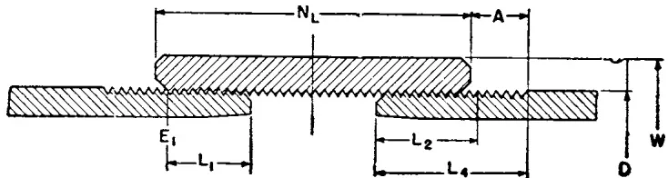
| Pipe | Threads | Coupling | ||||||||
| NPS Designator | DN Designator | Specified Outside Diameter, in. [mm] D | Number per inch | End of Pipe to Hand Tight Plane, in. [mm] L1 | Effective Length, in. [mm] L2 | Total Length, in. [mm] L4 | Pitch Diameter at Hand Tight Plane, in. [mm] E1 | Specified Outside Diameter, in. [mm] W | Length, min., in. [mm] NL | Hand Tight Stand-Off (Number of Threads) A |
| 1/8 | 6 | 0.405 [10.3] | 27 | 0.1615 [4.1021] | 0.2638 [6.7005] | 0.3924 [9.9670] | 0.37360 [9.48944] | 0.563 [14.3] | 3/4 [19] | 4 |
| 1/4 | 8 | 0.540 [13.7] | 18 | 0.2278 [5.7861] | 0.4018 [10.2057] | 0.5946 [15.1028] | 0.49163 [12.48740] | 0.719 [18.3] | 11/8 [29] | 51/2 |
| 3/8 | 10 | 0.675 [17.1] | 18 | 0.240 [6.096] | 0.4078 [10.3581] | 0.6006 [15.2552] | 0.62701 [15.92605] | 0.875 [22.2] | 11/8 [29] | 5 |
| 1/2 | 15 | 0.840 [21.3] | 14 | 0.320 [8.128] | 0.5337 [13.5560] | 0.7815 [19.8501] | 0.77843 [19.77212] | 1.063 [27.0] | 11/2 [38] | 5 |
| 3/4 | 20 | 1.050 [26.7] | 14 | 0.339 [8.611] | 0.5457 [13.8608] | 0.7935 [20.1549] | 0.98887 [25.11730] | 1.313 [33.4] | 19/16 [40] | 5 |
| 1 | 25 | 1.315 [33.4] | 111/2 | 0.400 [10.160] | 0.6828 [17.3431] | 0.9845 [25.0063] | 1.23863 [31.46120] | 1.576 [40.0] | 115/16 [49] | 5 |
| 11/4 | 32 | 1.660 [42.2] | 111/2 | 0.420 [10.668] | 0.7068 [17.9527] | 1.0085 [25.6159] | 1.58338 [40.21785] | 1.900 [48.3] | 2 [50] | 5 |
| 11/2 | 40 | 1.900 [48.3] | 111/2 | 0.420 [10.668] | 0.7235 [18.3769] | 1.0252 [26.0401] | 1.82234 [46.28744] | 2.200 [55.9] | 2 [50] | 51/2 |
| 2 | 50 | 2.375 [60.3] | 111/2 | 0.436 [11.074] | 0.7565 [19.2151] | 1.0582 [26.8783] | 2.29627 [58.32526] | 2.750 [69.8] | 21/16 [52] | 51/2 |
| 21/2 | 65 | 2.875 [73.0] | 8 | 0.682 [17.323] | 1.1376 [28.8950] | 1.5712 [39.9085] | 2.76216 [70.15886] | 3.250 [82.5] | 31/16 [78] | 51/2 |
| 3 | 80 | 3.500 [88.9] | 8 | 0.766 [19.456] | 1.2000 [30.4800] | 1.6337 [41.4960] | 3.38850 [86.06790] | 4.000 [101.6] | 33/16 [81] | 51/2 |
| 31/2 | 90 | 4.000 [101.6] | 8 | 0.821 [20.853] | 1.2500 [31.7500] | 1.6837 [42.7660] | 3.88881 [98.77577] | 4.625 [117.5] | 35/16 [84] | 51/2 |
| 4 | 100 | 4.500 [114.3] | 8 | 0.844 [21.438] | 1.3000 [33.0200] | 1.7337 [44.0360] | 4.38713 [111.43310] | 5.000 [127.0] | 37/16 [87] | 5 |
| 5 | 125 | 5.563 [141.3] | 8 | 0.937 [23.800] | 1.4063 [35.7200] | 1.8400 [46.7360] | 5.44929 [138.41200] | 6.296 [159.9] | 311/16 [94] | 5 |
| 6 | 150 | 6.625 [168.3] | 8 | 0.958 [24.333] | 1.5125 [38.4175] | 1.9462 [49.4335] | 6.50597 [165.25164] | 7.390 [187.7] | 315/16 [100] | 6 |
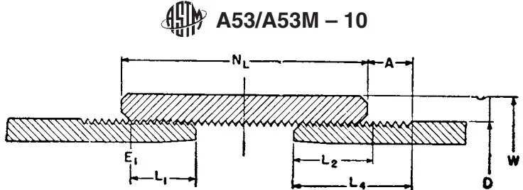
| Pipe | Threads | Coupling | |||||||||||||||
| NPS Designator | DN Designator | Specified Outside Diameter, in. | [mm] | Number per Inch | End of Pipe to Hand Tight Plane, in. | [mm] | Effective Length, in. | [mm] | Total Length, in. | [mm] | Pitch Diameter at Hand Tight Plane, in. | [mm] | Specified Outside Diameter, in. | [mm] | Length, min, in. | [mm] | Hand Tight Stand-Off (Number of Threads) |
| D | L1 | L2 | L4 | E1 | W | NL | |||||||||||
| 1/8 | 6 | 0.405 | [10.3] | 27 | 0.1615 | [4.1021] | 0.2638 | [6.7005] | 0.3924 | [9.9670] | 0.37360 | [9.48944] | 0.563 | [14.3] | 11/16 | [27] | 3 |
| 1/4 | 8 | 0.540 | [13.7] | 18 | 0.2278 | [5.7861] | 0.4018 | [10.2057] | 0.5946 | [15.1028] | 0.49163 | [12.48740] | 0.719 | [18.3] | 15/8 | [41] | 3 |
| 3/8 | 10 | 0.675 | [17.1] | 18 | 0.240 | [6.096] | 0.4078 | [10.3581] | 0.6006 | [15.2552] | 0.62701 | [15.92605] | 0.875 | [22.2] | 15/8 | [41] | 3 |
| 1/2 | 15 | 0.840 | [21.3] | 14 | 0.320 | [8.128] | 0.5337 | [13.5560] | 0.7815 | [19.8501] | 0.77843 | [19.77212] | 1.063 | [27.0] | 21/8 | [54] | 3 |
| 3/4 | 20 | 1.050 | [26.7] | 141/2 | 0.339 | [8.611] | 0.5457 | [13.8608] | 0.7935 | [20.1549] | 0.98887 | [25.11730] | 1.313 | [33.4] | 21/8 | [54] | 3 |
| 1 | 25 | 1.315 | [33.4] | 11 | 0.400 | [10.160] | 0.6828 | [17.3431] | 0.9845 | [25.0063] | 1.23863 | [31.46120] | 1.576 | [40.0] | 25/8 | [67] | 3 |
| 11/4 | 32 | 1.660 | [42.2] | 111/2 | 0.420 | [10.668] | 0.7068 | [17.9527] | 1.0085 | [25.6159] | 1.58338 | [40.21785] | 2.054 | [52.2] | 23/4 | [70] | 3 |
| 11/2 | 40 | 1.900 | [48.3] | 111/2 | 0.420 | [10.668] | 0.7235 | [18.3769] | 1.0252 | [26.0401] | 1.82234 | [46.28744] | 2.200 | [55.9] | 23/4 | [70] | 3 |
| 2 | 50 | 2.375 | [60.3] | 111/2 | 0.436 | [11.074] | 0.7565 | [19.2151] | 1.0582 | [26.8783] | 2.29627 | [58.32526] | 2.875 | [73.0] | 27/8 | [73] | 3 |
| 21/2 | 65 | 2.875 | [73.0] | 8 | 0.682 | [17.323] | 1.1375 | [28.8950] | 1.5712 | [39.9085] | 2.76216 | [70.15886] | 3.375 | [85.7] | 41/8 | [105] | 2 |
| 3 | 80 | 3.500 | [88.9] | 8 | 0.766 | [19.456] | 1.2000 | [30.4800] | 1.6337 | [41.4960] | 3.38850 | [86.06790] | 4.000 | [101.6] | 41/4 | [108] | 2 |
| 31/2 | 90 | 4.000 | [101.6] | 8 | 0.821 | [20.853] | 1.2500 | [31.7500] | 1.6837 | [42.7660] | 3.88881 | [98.77577] | 4.625 | [117.5] | 43/8 | [111] | 2 |
| 4 | 100 | 4.500 | [114.3] | 8 | 0.844 | [21.438] | 1.3000 | [33.0200] | 1.7337 | [44.0360] | 4.38713 | [111.43310] | 5.200 | [132.1] | 41/2 | [114] | 2 |
| 5 | 125 | 5.563 | [141.3] | 8 | 0.937 | [23.800] | 1.4063 | [35.7200] | 1.8400 | [46.7360] | 5.44929 | [138.41200] | 6.296 | [159.9] | 45/8 | [117] | 2 |
| 6 | 150 | 6.625 | [168.3] | 8 | 0.958 | [24.333] | 1.5125 | [38.4175] | 1.9462 | [49.4335] | 6.50597 | [165.25164] | 7.390 | [187.7] | 47/8 | [124] | 2 |
| 8 | 200 | 8.625 | [219.1] | 8 | 1.063 | [27.000] | 1.7125 | [43.4975] | 2.1462 | [54.5135] | 8.50003 | [215.90076] | 9.625 | [244.5] | 51/4 | [133] | 2 |
| 10 | 250 | 10.750 | [273.0] | 8 | 1.210 | [30.734] | 1.9250 | [48.8950] | 2.3587 | [59.9110] | 10.62094 | [269.77188] | 11.750 | [298.4] | 53/4 | [146] | 2 |
| 12 | 300 | 12.750 | [323.8] | 8 | 1.360 | [34.544] | 2.1250 | [53.9750] | 2.5587 | [64.9910] | 12.61781 | [320.49237] | 14.000 | [355.6] | 61/8 | [156] | 2 |
| 14 | 350 | 14.000 | [355.6] | 8 | 1.562 | [39.675] | 2.2500 | [57.1500] | 2.6837 | [68.1660] | 13.87263 | [352.36480] | 15.000 | [381.0] | 63/8 | [162] | 2 |
| 16 | 400 | 16.000 | [406.4] | 8 | 1.812 | [46.025] | 2.4500 | [62.2300] | 2.8837 | [73.2460] | 15.87575 | [403.24405] | 17.000 | [432] | 63/4 | [171] | 2 |
| 18 | 450 | 18.000 | [457] | 8 | 2.000 | [50.800] | 2.6500 | [67.3100] | 3.0837 | [78.3260] | 17.87500 | [454.02500] | 19.000 | [483] | 71/8 | [181] | 2 |
| 20 | 500 | 20.000 | [508] | 8 | 2.125 | [53.975] | 2.8500 | [72.3900] | 3.2837 | [83.4060] | 19.87031 | [504.70587] | 21.000 | [533] | 75/8 | [194] | 2 |
X4. ELONGATION VALUES
X4.1 Tabulated in Table X4.1 are the minimum elongation values in inch-pound units, calculated using the equation given in Table 2.
| Area, A, in.2 | Specified Wall Thickness, in. | Elongation in 2 in., min, % | |||
| 3⁄4-in.Specimen | Tension Test Specimen 1-in.Specimen | 11⁄2-in.Specimen | Specified Minimum Te48 000 | nsile Strength, psi60 000 | |
| 0.75 and | 0.994 and | 0.746 and | 0.497 and | 36 | 30 |
| greater | greater | greater | greater | ||
| 0.74 | 0.980-0.993 | 0.735-0.745 | 0.490-0.496 | 36 | 29 |
| 0.73 | 0.967-0.979 | 0.726-0.734 | 0.484-0.489 | 36 | 29 |
| 0.72 | 0.954-0.966 | 0.715-0.725 | 0.477-0.483 | 36 | 29 |
| 0.71 | 0.941-0.953 | 0.706-0.714 | 0.471-0.476 | 36 | 29 |
| 0.70 | 0.927-0.940 | 0.695-0.705 | 0.464-0.470 | 36 | 29 |
| 0.69 | 0.914-0.926 | 0.686-0.694 | 0.457-0.463 | 36 | 29 |
| 0.68 | 0.900-0.913 | 0.675-0.685 | 0.450-0.456 | 35 | 29 |
| 0.67 | 0.887-0.899 | 0.666-0.674 | 0.444-0.449 | 35 | 29 |
| 0.66 | 0.874-0.886 | 0.655-0.665 | 0.437-0.443 | 35 | 29 |
| Area, A, in.2 | Specified Wall Thickness, in. | Elongation in 2 in., min, % | |||
| Tension Test Specimen | Specified Minimum Tensile Strength, psi | ||||
| 3⁄4-in. Specimen | 1-in. Specimen | 11⁄2-in. Specimen | 48 000 | 60 000 | |
| 0.65 | 0.861–0.873 | 0.646–0.654 | 0.431–0.436 | 35 | 29 |
| 0.64 | 0.847–0.860 | 0.635–0.645 | 0.424–0.430 | 35 | 29 |
| 0.63 | 0.834–0.846 | 0.626–0.634 | 0.417–0.423 | 35 | 29 |
| 0.62 | 0.820–0.833 | 0.615–0.625 | 0.410–0.416 | 35 | 28 |
| 0.61 | 0.807–0.819 | 0.606–0.614 | 0.404–0.409 | 35 | 28 |
| 0.60 | 0.794–0.806 | 0.595–0.605 | 0.397–0.403 | 35 | 28 |
| 0.59 | 0.781–0.793 | 0.586–0.594 | 0.391–0.396 | 34 | 28 |
| 0.58 | 0.767–0.780 | 0.575–0.585 | 0.384–0.390 | 34 | 28 |
| 0.57 | 0.754–0.766 | 0.566–0.574 | 0.377–0.383 | 34 | 28 |
| 0.56 | 0.740–0.753 | 0.555–0.565 | 0.370–0.376 | 34 | 28 |
| 0.55 | 0.727–0.739 | 0.546–0.554 | 0.364–0.369 | 34 | 28 |
| 0.54 | 0.714–0.726 | 0.535–0.545 | 0.357–0.363 | 34 | 28 |
| 0.53 | 0.701–0.713 | 0.526–0.534 | 0.351–0.356 | 34 | 28 |
| 0.52 | 0.687–0.700 | 0.515–0.525 | 0.344–0.350 | 34 | 27 |
| 0.51 | 0.674–0.686 | 0.506–0.514 | 0.337–0.343 | 33 | 27 |
| 0.50 | 0.660–0.673 | 0.495–0.505 | 0.330–0.336 | 33 | 27 |
| 0.49 | 0.647–0.659 | 0.486–0.494 | 0.324–0.329 | 33 | 27 |
| 0.48 | 0.634–0.646 | 0.475–0.485 | 0.317–0.323 | 33 | 27 |
| 0.47 | 0.621–0.633 | 0.466–0.474 | 0.311–0.316 | 33 | 27 |
| 0.46 | 0.607–0.620 | 0.455–0.465 | 0.304–0.310 | 33 | 27 |
| 0.45 | 0.594–0.606 | 0.446–0.454 | 0.297–0.303 | 33 | 27 |
| 0.44 | 0.580–0.593 | 0.435–0.445 | 0.290–0.296 | 32 | 27 |
| 0.43 | 0.567–0.579 | 0.426–0.434 | 0.284–0.289 | 32 | 26 |
| 0.42 | 0.554–0.566 | 0.415–0.425 | 0.277–0.283 | 32 | 26 |
| 0.41 | 0.541–0.553 | 0.406–0.414 | 0.271–0.276 | 32 | 26 |
| 0.40 | 0.527–0.540 | 0.395–0.405 | 0.264–0.270 | 32 | 26 |
| 0.39 | 0.514–0.526 | 0.386–0.394 | 0.257–0.263 | 32 | 26 |
| 0.38 | 0.500–0.513 | 0.375–0.385 | 0.250–0.256 | 32 | 26 |
| 0.37 | 0.487–0.499 | 0.366–0.374 | 0.244–0.249 | 31 | 26 |
| 0.36 | 0.474–0.486 | 0.355–0.365 | 0.237–0.243 | 31 | 26 |
| 0.35 | 0.461–0.473 | 0.346–0.354 | 0.231–0.236 | 31 | 25 |
| 0.34 | 0.447–0.460 | 0.335–0.345 | 0.224–0.230 | 31 | 25 |
| 0.33 | 0.434–0.446 | 0.326–0.334 | 0.217–0.223 | 31 | 25 |
| 0.32 | 0.420–0.433 | 0.315–0.325 | 0.210–0.216 | 30 | 25 |
| 0.31 | 0.407–0.419 | 0.306–0.314 | 0.204–0.209 | 30 | 25 |
| 0.30 | 0.394–0.406 | 0.295–0.305 | 0.197–0.203 | 30 | 25 |
| 0.29 | 0.381–0.393 | 0.286–0.294 | 0.191–0.196 | 30 | 24 |
| 0.28 | 0.367–0.380 | 0.275–0.285 | 0.184–0.190 | 30 | 24 |
| 0.27 | 0.354–0.366 | 0.266–0.274 | 0.177–0.183 | 29 | 24 |
| 0.26 | 0.340–0.353 | 0.255–0.265 | 0.170–0.176 | 29 | 24 |
| 0.25 | 0.327–0.339 | 0.246–0.254 | 0.164–0.169 | 29 | 24 |
| 0.24 | 0.314–0.326 | 0.235–0.245 | 0.157–0.163 | 29 | 24 |
| 0.23 | 0.301–0.313 | 0.226–0.234 | 0.151–0.156 | 29 | 23 |
| 0.22 | 0.287–0.300 | 0.215–0.225 | 0.144–0.150 | 28 | 23 |
| 0.21 | 0.274–0.286 | 0.260–0.214 | 0.137–0.143 | 28 | 23 |
| 0.20 | 0.260–0.273 | 0.195–0.205 | 0.130–0.136 | 28 | 23 |
| 0.19 | 0.247–0.259 | 0.186–0.194 | 0.124–0.129 | 27 | 22 |
| 0.18 | 0.234–0.246 | 0.175–0.185 | 0.117–0.123 | 27 | 22 |
| 0.17 | 0.221–0.233 | 0.166–0.174 | 0.111–0.116 | 27 | 22 |
| 0.16 | 0.207–0.220 | 0.155–0.165 | 0.104–0.110 | 27 | 22 |
| 0.15 | 0.194–0.206 | 0.146–0.154 | 0.097–0.103 | 26 | 21 |
| 0.14 | 0.180–0.193 | 0.135–0.145 | 0.091–0.096 | 26 | 21 |
| 0.13 | 0.167–0.179 | 0.126–0.134 | 0.084–0.090 | 25 | 21 |
| 0.12 | 0.154–0.166 | 0.115–0.125 | 0.077–0.083 | 25 | 20 |
| 0.11 | 0.141–0.153 | 0.106–0.114 | 0.071–0.076 | 25 | 20 |
| 0.10 | 0.127–0.140 | 0.095–0.105 | 0.064–0.070 | 24 | 20 |
| 0.09 | 0.114–0.126 | 0.086–0.094 | 0.057–0.063 | 24 | 19 |
| 0.08 | 0.100–0.113 | 0.075–0.085 | 0.050–0.056 | 23 | 19 |
| 0.07 | 0.087–0.099 | 0.066–0.074 | 0.044–0.049 | 22 | 18 |
| 0.06 | 0.074–0.086 | 0.055–0.065 | 0.037–0.043 | 22 | 18 |
| 0.05 | 0.061–0.073 | 0.046–0.054 | 0.031–0.036 | 21 | 17 |
| 0.04 | 0.047–0.060 | 0.035–0.045 | 0.024–0.030 | 20 | 16 |
| 0.03 | 0.034–0.046 | 0.026–0.034 | 0.017–0.023 | 19 | 16 |
| 0.02 | 0.020–0.033 | 0.015–0.025 | 0.010–0.016 | 17 | 14 |
| 0.01 and less | 0.019 and less | 0.014 and less | 0.009 and less | 15 | 12 |
X4.2 Tabulated in Table X4.2 are the minimum elongation values in SI units, calculated using the equation given in Table 2.
| Area, A, mm2 | Specified Wall Thickness, mm | Elongation in 50 mm, min, % | |||
| Tension Test Specimen | Specified Minimum Tensile Strength, MPa | ||||
| 19-mm Specimen | 25-mm Specimen | 38-mm Specimen | 330 | 415 | |
| 500 and greater | 26.3 and greater | 20.0 and greater | 13.2 and greater | 36 | 30 |
| 480-499 | 25.3-26.2 | 19.2-19.9 | 12.7-13.1 | 36 | 30 |
| 460-479 | 24.2-25.2 | 18.4-19.1 | 12.1-12.6 | 36 | 29 |
| 440-459 | 23.2-24.1 | 17.6-18.3 | 11.6-12.0 | 36 | 29 |
| 420-439 | 22.1-23.1 | 16.8-17.5 | 11.1-11.5 | 35 | 29 |
| 400-419 | 21.1-22.0 | 16.0-16.7 | 10.6-11.0 | 35 | 29 |
| 380-399 | 20.0-21.0 | 15.2-15.9 | 10.0-10.5 | 35 | 28 |
| 360-379 | 19.0-19.9 | 14.4-15.0 | 9.5-9.9 | 34 | 28 |
| 340-359 | 17.9-18.9 | 13.6-14.3 | 9.0-9.4 | 34 | 28 |
| 320-339 | 16.9-17.8 | 12.8-13.5 | 8.5-8.9 | 34 | 27 |
| 300-319 | 15.8-16.8 | 12.0-12.7 | 7.9-8.4 | 33 | 27 |
| 280-299 | 14.8-15.7 | 11.2-11.9 | 7.4-7.8 | 33 | 27 |
| 260-279 | 13.7-14.7 | 10.4-11.1 | 6.9-7.3 | 32 | 26 |
| 240-259 | 12.7-13.6 | 9.6-10.3 | 6.4-6.8 | 32 | 26 |
| 220-239 | 11.6-12.6 | 8.8-9.5 | 5.8-6.3 | 31 | 26 |
| 200-219 | 10.5-11.5 | 8.0-8.7 | 5.3-5.7 | 31 | 25 |
| 190-199 | 10.0-10.4 | 7.6-7.9 | 5.0-5.2 | 30 | 25 |
| 180-189 | 9.5-9.9 | 7.2-7.5 | 4.8-4.9 | 30 | 24 |
| 170-179 | 9.0-9.4 | 6.8-7.1 | 4.5-4.7 | 30 | 24 |
| 160-169 | 8.4-8.9 | 6.4-6.7 | 4.2-4.4 | 29 | 24 |
| 150-159 | 7.9-8.3 | 6.0-6.3 | 4.0-4.1 | 29 | 24 |
| 140-149 | 7.4-7.8 | 5.6-5.9 | 3.7-3.9 | 29 | 23 |
| 130-139 | 6.9-7.3 | 5.2-5.5 | 3.5-3.6 | 28 | 23 |
| 120-129 | 6.3-6.8 | 4.8-5.1 | 3.2-3.4 | 28 | 23 |
| 110-119 | 5.8-6.2 | 4.4-4.7 | 2.9-3.1 | 27 | 22 |
| 100-109 | 5.3-5.7 | 4.0-4.3 | 2.7-2.8 | 27 | 22 |
| 90-99 | 4.8-5.2 | 3.6-3.9 | 2.4-2.6 | 26 | 21 |
| 80-89 | 4.2-4.7 | 3.2-3.5 | 2.1-2.3 | 26 | 21 |
| 70-79 | 3.7-4.1 | 2.8-3.1 | 1.9-2.0 | 25 | 21 |
| 60-69 | 3.2-3.6 | 2.4-2.7 | 1.6-1.8 | 24 | 20 |
| 50-59 | 2.7-3.1 | 2.0-2.3 | ... | 24 | 19 |
| 40-49 | 2.1-2.6 | 1.6-1.9 | ... | 23 | 19 |
| 30-39 | 1.6-2.0 | ... | ... | 22 | 18 |
评论