


1 Scope*
1.1 This specification covers poly(vinyl chloride) (PVC) Schedule 40 pipe fittings. Included are requirements for materials, workmanship, dimensions, and burst pressure.
NOTE 1—Socket-type CPVC plastic pipe fittings, Schedule 40, which were formerly included in this standard, are now covered by Specification F438.
1.2 The products covered by this specification are intended for use with the distribution of pressurized liquids only, which are chemically compatible with the piping materials. Due to inherent hazards associated with testing components and systems with compressed air or other compressed gases, some manufacturers do not allow pneumatic testing of their products. Consult with specific product/component manufacturers for their specific testing procedures prior to pneumatic testing.
NOTE 2—Pressurized (compressed) air or other compressed gases contain large amounts of stored energy which present serious saftey hazards should a system fail for any reason.
1.3 Fitting such as unions, flanges, special plastic-to-metal transitions and appurtenances intended for use with PVC piping are covered under specification F1970.
1.4 The text of this specification references notes, footnotes, and appendixes which provide explanatory material. These notes and footnotes (excluding those in tables and figures) shall not be considered as requirements of the specification.
1.5 The values stated in inch-pound units are to be regarded as standard. The values given in parentheses are mathematical conversions to SI units that are provided for information only and are not considered standard.
1.6 The following safety hazards caveat pertains only to the test method portion, Section 7, of this specification. This standard does not purport to address all of the safety concerns, if any, associated with its use. It is the responsibility of the user
of this standard to establish appropriate safety and health practices and determine the applicability of regulatory limitations prior to use.
1.7 This international standard was developed in accordance with internationally recognized principles on standardization established in the Decision on Principles for the Development of International Standards, Guides and Recommendations issued by the World Trade Organization Technical Barriers to Trade (TBT) Committee.
2 Referenced Documents
2.1 ASTM Standards:
2
D618 Practice for Conditioning Plastics for Testing
D1599 Test Method for Resistance to Short-Time Hydraulic Pressure of Plastic Pipe, Tubing, and Fittings
D1600 Terminology for Abbreviated Terms Relating to Plastics
D1784 Specification for Rigid Poly(Vinyl Chloride) (PVC) Compounds and Chlorinated Poly(Vinyl Chloride) (CPVC) Compounds
D2122 Test Method for Determining Dimensions of Thermoplastic Pipe and Fittings
D2749 Symbols for Dimensions of Plastic Pipe Fittings
F412 Terminology Relating to Plastic Piping Systems
F438 Specification for Socket-Type Chlorinated Poly(Vinyl Chloride) (CPVC) Plastic Pipe Fittings, Schedule 40
F1498 Specification for Taper Pipe Threads 60° for Thermoplastic Pipe and Fittings
F1970 Specification for Special Engineered Fittings, Appurtenances or Valves for use in Poly (Vinyl Chloride) (PVC) or Chlorinated Poly (Vinyl Chloride) (CPVC) Systems
2.2 NSF Standards:
Standard No. 14 for Plastic Piping Components and Related Materials
3
1 This specification is under the jurisdiction of ASTM Committee F17 on Plastic Piping Systems and is the direct responsibility of Subcommittee F17.10 on Fittings.
Current edition approved Aug. 1, 2017. Published August 2017. Originally approved in 1965. Last previous edition approved in 2015 as D2466 – 15. DOI: 10.1520/D2466-17.
2 For referenced ASTM standards, visit the ASTM website, www.astm.org, or contact ASTM Customer Service at service@astm.org. For Annual Book of ASTM Standards volume information, refer to the standard’s Document Summary page on the ASTM website.
3 Available from NSF International, P.O. Box 130140, 789 N. Dixboro Rd., Ann Arbor, MI 48113-0140, http://www.nsf.org.
Standard No. 61 for Drinking Water Systems Components— Health Effects
3 Terminology
3.1 General—Definitions are in accordance with Terminology F412, and abbreviations are in accordance with Terminology D1600, unless otherwise indicated. The abbreviation for poly(vinyl chloride) plastic is PVC.
4 Classification
4.1 General—This specification covers Schedule 40 PVC pipe fittings, made from four PVC plastic compounds and intended for use with Iron Pipe Size (IPS) outside-diameter plastic pipe.
4.1.1 Fittings covered by this specification are normally molded. In-line fittings, such as couplings, bushings, caps, nipples, etc., shall be molded or machined from extruded stock.
4.1.2 Fittings fabricated by welding are not included in this specification.
5 Materials
5.1 This specification covers PVC pipe fittings made from five PVC plastics as classified in Specification D1784. These are PVC 12454, 12454, 13354, 11443, and 14333.
5.2 Compound—The PVC plastic compound shall meet the requirements of PVC 12454, 12454, 11443, or 14333, as described in Specification D1784. NOTE 3—Mechanical strength, heat resistance, flammability, and chemical resistance requirements are covered in Specification D1784.
5.3 Rework Material—The manufacturers shall use only their own clean rework fitting material and the fittings produced shall meet all the requirements of this specification.
6 Requirements
6.1 Dimensions and Tolerances:
6.1.1 Fitting sockets inside diameters (waterways), minimum wall thicknesses, and dimensions shall be as shown in Table 1, Table 2, and Table 3 when measured in accordance with Test Method D2122.
6.1.2 When multistep reducer bushings are cored out, the inner socket shall be reinforced from the outer wall by a minimum of three ribs extending from the top of the inner socket to the deepest extremity of the coring. The transition from D to DJ (Table 3) shall be straight, tapered as shown, or radiused. A positive taper in the same direction of the taper in the socket on the outside diameter of the bushing is optional (See XA/XB in Table 3). Any point measured along the outside diameter of the bushing (between points XA and XB) shall not fall below minimum pipe OD.
6.1.3 The minimum wall thickness of fittings shall be 125 % of the minimum wall thickness of the corresponding size of Schedule 40 pipe for which they are designed to be used, except that for the socket, the wall thickness shall be at least equal to the minimum wall thickness of the corresponding size of Schedule 40 pipe. For any threaded fitting the minimum wall thickness of the threaded portion shall be at least equal to the thickness of material under the thread root of threaded Schedule 80 pipe of the same size.
6.1.4 The minimum inside diameter of the fittings shall be not less than the minimum specified inside diameter of the corresponding size of Schedule 40 pipe. Any fitting having a male thread shall have an internal diameter not larger than Schedule 80 pipe of the same size.
6.1.5 Minimum dimensions have zero negative tolerance. Tolerances on other dimensions are shown in Table 1 and Table 3.
6.2 Threads—For all fittings having taper pipe threads, threads shall conform to Specification F1498 and be gaged in accordance with 8.4.
6.3 Burst Pressure:
6.3.1 The minimum burst strength of the fittings shall be not less than that calculated for the size and wall thickness of the pipe with which it is to be used, when calculated from the following equation:
S = P (Do - t ) /2t(1)
where:
S = hoop stress, psi (or MPa),
P = internal pressure, psi (or MPa),
D
O = average outside diameter, in. (or mm), and
t = minimum wall thickness, in. (or mm).
Fittings tested in accordance with 8.5 shall withstand the minimum burst pressure shown in Table 4.
6.3.2 Pressures shown are minimum burst pressures and do not imply rated working pressures. The burst pressure shall be used only as an indication of quality.
7 Workmanship, Finish, and Appearance
7.1 The fittings shall be homogeneous throughout and free of cracks, holes, foreign inclusions, or other defects. The fittings shall be as uniform as commercially practicable in color, opacity, density, and other physical properties.
8 Test Methods
8.1 Conditioning—Condition the test specimens at 73 6 3.6°F (23 6 2°C) and 50 6 10 % relative humidity for not less than 40 h prior to test in accordance with Procedure A of Practice D618, for those tests where conditioning is required.
8.2 Test Conditions—Conduct tests in the Standard Laboratory Atmosphere of 73 6 3.6°F (23 6 2°C) and 50 6 10 % relative humidity, unless otherwise specified in the test methods or in this specification.
8.3 Sampling—A sufficient quantity of fittings as agreed upon between the seller and the purchaser shall be selected at random from each lot or shipment and tested to determine that the basic design is in conformance with this specification. NOTE 4—For individual orders or specifications, only those tests and numbers of tests specifically agreed upon between the purchaser and the seller need be conducted.
8.4 Threads—All taper pipe threads shall be gaged in accordance with Specification F1498.
8.5 Burst Pressure—Determine the minimum burst pressure in accordance with Test Method D1599, Procedure B. The TABLE 1 Tapered Sockets for PVC Pipe Fittings, Schedule 40, in.
A
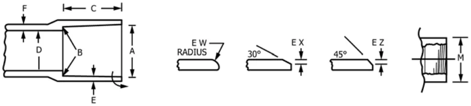
| Nominal Pipe Size | A Socket Entrance Diameter | B Socket Bottom Diameter | CBSocket Length, min | DCInside Diameter, min | Wall Thickness, min | Min Outside Diameter of Hub, M | Entrance, min | ||||||
| Diameter | Tolerance on Diameter | Max Out-of-Round | Diameter | Tolerance on Diameter | Max Out-of-Round | E | F | EW | EX, EZ | ||||
| 1/8 | 0.417 | ±0.004 | 0.016(0.41) | 0.401 | ±0.004 | 0.016(0.41) | 0.500 | 0.225 | 0.068 | 0.085 | 0.526 | 1/64 | 1/64 |
| 1/4 | 0.552 | ±0.004 | 0.016(0.41) | 0.536 | ±0.004 | 0.016(0.41) | 0.500 | 0.320 | 0.088 | 0.110 | 0.672 | 1/64 | 1/64 |
| 3/8 | 0.687 | ±0.004 | 0.016(0.41) | 0.671 | ±0.004 | 0.016(0.41) | 0.594 | 0.449 | 0.091 | 0.114 | 0.821 | 1/32 | 1/32 |
| 1/2 | 0.848 | ±0.004 | 0.016(0.41) | 0.836 | ±0.004 | 0.016(0.41) | 0.688 | 0.578 | 0.109 | 0.136 | 0.998 | 1/32 | 1/32 |
| 3/4 | 1.058 | ±0.004 | 0.020(0.51) | 1.046 | ±0.004 | 0.020(0.51) | 0.719 | 0.740 | 0.113 | 0.141 | 1.221 | 1/32 | 1/32 |
| 1 | 1.325 | ±0.005 | 0.020(0.51) | 1.310 | ±0.005 | 0.020(0.51) | 0.875 | 0.990 | 0.133 | 0.166 | 1.504 | 1/16 | 1/16 |
| 11/4 | 1.670 | ±0.005 | 0.024(0.61) | 1.655 | ±0.005 | 0.024(0.61) | 0.938 | 1.335 | 0.140 | 0.175 | 1.871 | 1/16 | 1/16 |
| 11/2 | 1.912 | ±0.006 | 0.024(0.61) | 1.894 | ±0.006 | 0.024(0.61) | 1.094 | 1.564 | 0.145 | 0.181 | 2.127 | 1/16 | 1/16 |
| 2 | 2.387 | ±0.006 | 0.024(0.61) | 2.369 | ±0.006 | 0.024(0.61) | 1.156 | 2.021 | 0.154 | 0.193 | 2.634 | 1/16 | 1/16 |
| 21/2 | 2.889 | ±0.007 | 0.030(0.76) | 2.868 | ±0.007 | 0.030(0.76) | 1.750 | 2.414 | 0.203 | 0.254 | 3.170 | 3/32 | 1/8 |
| 3 | 3.516 | ±0.008 | 0.030(0.76) | 3.492 | ±0.008 | 0.030(0.76) | 1.875 | 3.008 | 0.216 | 0.270 | 3.841 | 3/32 | 1/8 |
| 31/2 | 4.016 | ±0.008 | 0.030(0.76) | 3.992 | ±0.008 | 0.030(0.76) | 2.000 | 3.486 | 0.226 | 0.283 | 4.374 | 3/32 | 1/8 |
| 4 | 4.518 | ±0.009 | 0.030(0.76) | 4.491 | ±0.009 | 0.030(0.76) | 2.000 | 3.961 | 0.237 | 0.296 | 4.907 | 3/32 | 1/8 |
| 5 | 5.583 | ±0.010 | 0.060(1.52) | 5.553 | ±0.010 | 0.060(1.52) | 3.000 | 4.975 | 0.258 | 0.323 | 6.039 | 3/32 | 1/8 |
| 6 | 6.647 | ±0.011 | 0.060(1.52) | 6.614 | ±0.011 | 0.060(1.52) | 3.000 | 5.986 | 0.280 | 0.350 | 7.203 | 1/8 | 3/16 |
| 8 | 8.655 | ±0.015 | 0.090(2.29) | 8.610 | ±0.015 | 0.090(2.29) | 4.000 | 7.888 | 0.322 | 0.403 | 9.320 | 1/8 | 3/16 |
| 10 | 10.780 | ±0.015 | 0.100(3.05) | 10.735 | ±0.015 | 0.100(3.05) | 5.000 | 9.917 | 0.365 | 0.456 | 11.614 | 1/8 | 3/16 |
| 12 | 12.780 | ±0.015 | 0.120(3.81) | 12.735 | ±0.015 | 0.120(3.81) | 6.000 | 11.825 | 0.406 | 0.508 | 13.786 | 1/8 | 3/16 |
pressure shall be applied at a uniform rate such that the minimum allowable burst pressure is attained in 60 to 70 s. NOTE 5—Provided the minimum burst pressure is met or exceeded between 60 and 70 s, the time-to-failure may exceed 70 s.
9 Retest and Rejection
9.1 If the results of any test(s) do not meet the requirements of this specification, the tests(s) shall be conducted again only by agreement between the purchaser and seller. Under such agreement, minimum requirements shall not be lowered, changed, or modified, nor shall specification limits be changed.
If upon retest, failure occurs, the quantity of product represented by the test(s) does not meet the requirements of this specification.
10 Marking
10.1 Fittings shall be marked with the following:
10.1.1 Manufacturer’s name or trademark,
10.1.2 Material designation PVC I for PVC 12454-B, PVC 12 for PVC 12454-C, PVC 13 for PVC 13354-C and 11443-B, and PVC II for PVC 14333-D,

TABLE 2 Minimum Dimension from Center to End of Sockets (Laying Length) for Couplings, Tees, 90° and 45° Elbows, PVC Socket-Type Pipe Fittings, Schedule 40, in.
A
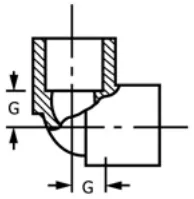
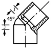
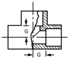
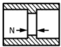
| Nominal Pipe Size | G, min | J, min | N, min |
| 1⁄8 | 1⁄4 | 1⁄8 | 1⁄16 |
| 1⁄4 | 5⁄16 | 5⁄32 | 1⁄16 |
| 3⁄8 | 3⁄8 | 3⁄16 | 3⁄32 |
| 1⁄2 | 1⁄2 | 1⁄4 | 3⁄32 |
| 3⁄4 | 9⁄16 | 5⁄16 | 3⁄32 |
| 1 | 11⁄16 | 5⁄16 | 3⁄32 |
| 11⁄4 | 7⁄8 | 3⁄8 | 3⁄32 |
| 11⁄2 | 1 | 7⁄16 | 3⁄32 |
| 2 | 11⁄4 | 5⁄8 | 3⁄32 |
| 21⁄2 | 11⁄2 | 11⁄16 | 3⁄16 |
| 3 | 113⁄16 | 3⁄4 | 3⁄16 |
| 31⁄2 | 21⁄8 | 1 | 3⁄16 |
| 4 | 25⁄16 | 1 | 3⁄16 |
| 5 | 3 | 13⁄8 | 3⁄16 |
| 6 | 31⁄2 | 13⁄4 | 1⁄4 |
| 8 | 41⁄2 | 2 | 1⁄4 |
| 10 | 513⁄16 | 29⁄16 | 1⁄4 |
| 12 | 615⁄16 | 31⁄16 | 1⁄4 |
10.1.3 Fittings intended for the transport of potable water shall include the seal or mark of the laboratory making the evaluation for this purpose.
10.1.4 Size, and
10.1.5 This designation number: D2466.
10.2 Where the size of the fitting does not allow complete marking, omit identification marking in the following sequence: size, material designation, manufacturer’s name or trademark.
10.3 Markings or symbols shall be molded, hot-stamped, or applied to fittings by any other suitable method, such as printing.
10.4 Where recessed marking is used, care shall be taken to see that in no case marking causes cracks or reduces the wall thickness below the minimum specified.
11 Quality Assurance
11.1 When the product is marked with this designation, D2466, the manufacturer affirms that the product was manufactured, inspected, sampled, and tested in accordance with this specification and has been found to meet the requirements of this specification.
12 Keywords
12.1 fittings; pressure; PVC; Sch 40; sockets; threads
1 D2466 − 17
TABLE 3 Dimensions of Reducer Bushings, PVC Socket-Type Pipe Fittings, Schedule 40,
A
in. (mm)
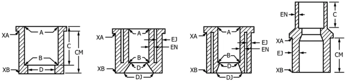
| Nominal Size | Outside Diameter XA | Tolerance on Outside Diameter | Outside Diameter XB | Tolerance on Outside Diameter | Maximum Out-of-Roundness (max, minus min.) |
| 1⁄4 by 1⁄8 | 0.540 (13.72) | +0.007 - 0.004 (0.18 - 0.10) | 0.540 (13.72) | ±0.004 (0.10) | 0.016 (0.41) |
| 3⁄8 by 1⁄4, 1⁄8 | 0.675 (17.41) | +0.007 - 0.004 (0.18 - 0.10) | 0.675 (17.41) | ±0.004 (0.10) | 0.016 (0.41) |
| 1⁄2 by 3⁄8, 1⁄4 | 0.840 (21.34) | +0.007 - 0.004 (0.18 - 0.10) | 0.840 (21.34) | ±0.004 (0.10) | 0.016 (0.41) |
| 3⁄4 by 1⁄2, 3⁄8, 1⁄4 | 1.050 (26.67) | +0.007 - 0.004 (0.18 - 0.10) | 1.050 (26.67) | ±0.004 (0.10) | 0.020 (0.51) |
| 1 by 1⁄2, 3⁄4 | 1.315 (33.40) | +0.008 - 0.005 (0.20 - 0.13) | 1.315 (33.40) | ±0.005 (0.13) | 0.020 (0.51) |
| 11⁄4 by 1⁄2, 3⁄4, 1 | 1.660 (42.16) | +0.008 - 0.005 (0.20 - 0.13) | 1.660 (42.16) | ±0.005 (0.13) | 0.024 (0.61) |
| 11⁄2 by 1⁄2, 3⁄4, 1, 11⁄4 | 1.900 (48.26) | +0.010 - 0.006 (0.25 - 0.15) | 1.900 (48.26) | ±0.006 (0.15) | 0.024 (0.61) |
| 2 by 1⁄2, 3⁄4, 1, 11⁄4, 11⁄2 | 2.375 (60.33) | +0.010 - 0.006 (0.25 - 0.15) | 2.375 (60.33) | ±0.006 (0.15) | 0.024 (0.61) |
| 21⁄2 by 2 | 2.875 (73.03) | +0.012 - 0.007 (0.30 - 0.18) | 2.875 (73.03) | ±0.007 (0.18) | 0.030 (0.76) |
| 3 by 21⁄2, 2 | 3.500 (88.90) | +0.013 - 0.008 (0.33 - 0.20) | 3.500 (88.90) | ±0.008 (0.20) | 0.030 (0.76) |
| 31⁄2 by 21⁄2, 2 | 4.000 (101.60) | +0.013 - 0.008 (0.33 - 0.20) | 4.000 (101.60) | ±0.008 (0.20) | 0.030 (0.76) |
| 4 by 31⁄2, 3, 21⁄2, 2 | 4.500 (114.30) | +0.015 - 0.009 (0.38 - 0.23) | 4.500 (114.30) | ±0.009 (0.23) | 0.030 (0.76) |
| 5 by 4 | 5.563 (141.30) | +0.017 - 0.010 (0.43 - 0.25) | 5.563 (141.30) | ±0.010 (0.25) | 0.060 (1.52) |
| 6 by 5 | 6.625 (168.28) | +0.018 - 0.011 (0.46 - 0.28) | 6.625 (168.28) | ±0.011 (0.28) | 0.070 (1.78) |
| 8 by 6 | 8.625 (219.08) | +0.025 - 0.015 (0.64 - 0.38) | 8.625 (219.08) | ±0.015 (0.38) | 0.090 (2.29) |
| 10 by 6 | 10.750 (273.05) | +0.025 - 0.015 (0.64 - 0.38) | 10.750 (273.05) | ±0.015 (0.38) | 0.100 (2.54) |
| 10 by 8 | 10.750 (273.05) | +0.025 - 0.015 (0.64 - 0.38) | 10.750 (273.05) | ±0.015 (0.38) | 0.100 (2.54) |
| 12 by 6 | 12.750 (323.85) | +0.025 - 0.015 (0.64 - 0.38) | 12.750 (323.85) | ±0.015 (0.38) | 0.120 (3.05) |
| 12 by 8 | 12.750 (323.85) | +0.025 - 0.015 (0.64 - 0.38) | 12.750 (323.85) | ±0.015 (0.38) | 0.120 (3.05) |
| 12 by 10 | 12.750 (323.85) | +0.025 - 0.015 (0.64 - 0.38) | 12.750 (323.85) | ±0.015 (0.38) | 0.120 (3.05) |
| Nominal Size, in. | Min Burst Strength,A | |||
| Classes 12454, 1 psi | 3354-C, and 11443 (MPa) | psi | Class 14333 (MPa) | |
| 1⁄8 | 2580 | (17.79) | 2020 | (13.93) |
| 1⁄4 | 2490 | (17.17) | 1950 | (13.44) |
| 3⁄8 | 1990 | (13.72) | 1560 | (10.76) |
| 1⁄2 | 1910 | (13.17) | 1490 | (10.27) |
| 3⁄4 | 1540 | (10.62) | 1210 | (8.34) |
| 1 | 1440 | (9.93) | 1130 | (7.79) |
| 11⁄4 | 1180 | (8.14) | 920 | (6.34) |
| 11⁄2 | 1060 | (7.31) | 830 | (5.72) |
| 2 | 890 | (6.14) | 690 | (4.76) |
| 21⁄2 | 970 | (6.69) | 760 | (5.24) |
| 3 | 840 | (5.79) | 660 | (4.55) |
| 31⁄2 | 770 | (5.31) | 600 | (4.14) |
| 4 | 710 | (4.90) | 560 | (3.86) |
| 5 | 620 | (4.27) | 490 | (3.38) |
| 6 | 560 | (3.86) | 440 | (3.03) |
| 8 | 500 | (3.45) | 390 | (2.69) |
| 10 | 450 | 3.10 | . . . | . . . |
| 12 | 420 | 2.90 | . . . | . . . |
评论